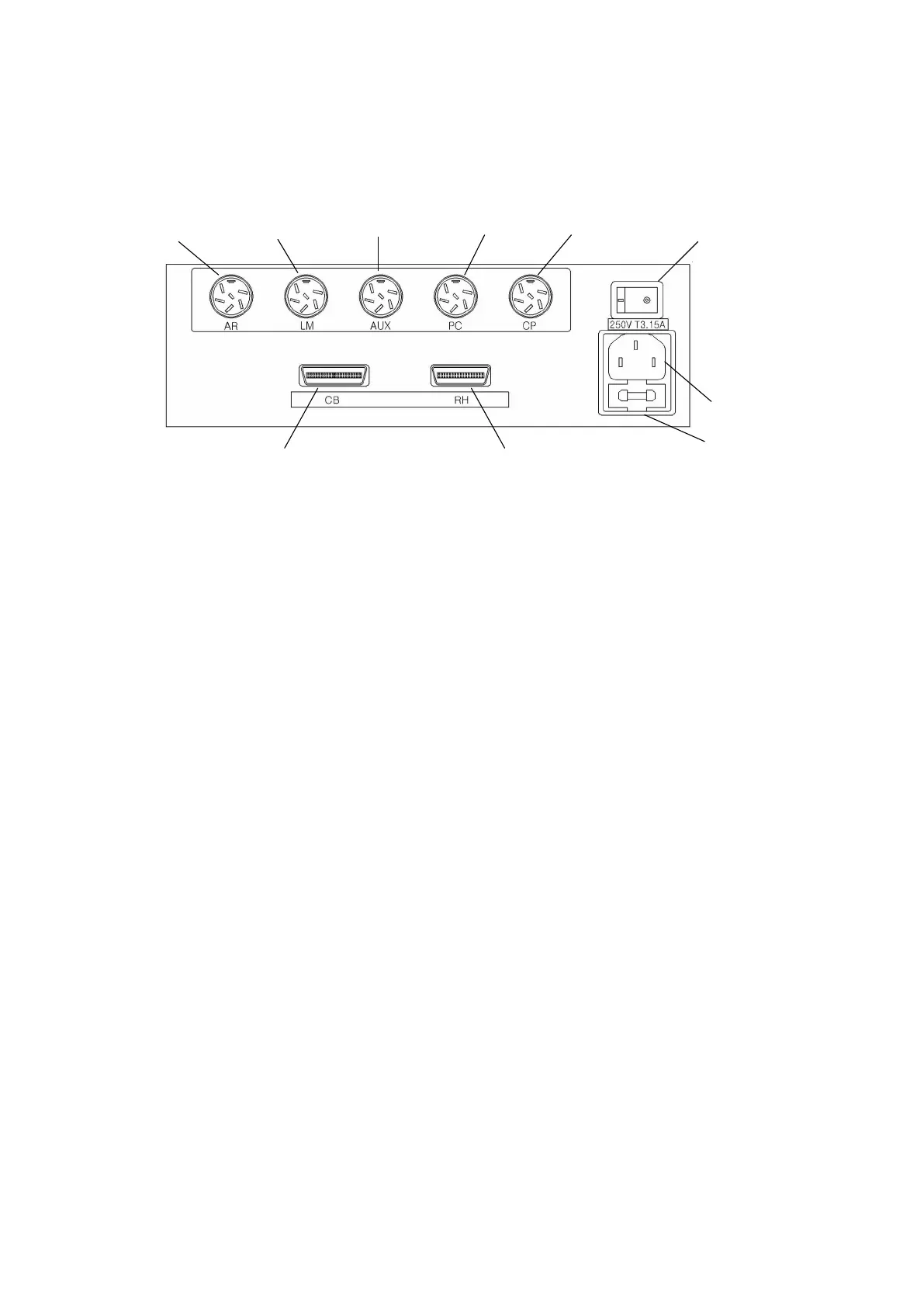
1. RK connector
Connects to an auto Ref/Keratometer(PRK-5000, PRK-5000L, PRK-6000, PRK-7000,
PRK-8000).
2. LM connector
Connects to a lensmeter(PLM-6100, PLM-8000).
3. AUX connector
Auxiliary (AUX) communication connector.
4. PC connector
Connects to a PC.
5. CP connector
Connects to a chart presenting device (PACP-7000, PACP-7000L, PLC-7000,
PLC-7000pola, PLC-7100, PLC-7100pola, PLC-8000, PLC-8000pola).
6. CB connector
Connects to the control box(CB).
7. RH connector
Connects to the refractor head(RH).
SAFEYT INFORMATION: Accessory equipment connected to the analog and digital
interfaces must be certificated according to the respective IEC standards (e.g. IEC
60950-1 for data processing equipment and IEC 60601-1 for medical equipment).
Furthermore all configurations shall comply with the system standard EN 60601-
1:2006, Clause 16. Everybody who connects additional equipment to the signal input
part or signal output part configures a medical system, and is therefore responsible
that the system complies with the requirements of the system standard (IEC 601-1-1
) IEC 60601-1:2005, Clause 16. If in doubt, consult the technical service department
or your local representative.
- 11 -