5–73Replacement Procedures
4
5
6
10
1
3
2 Places
7
9
NOTE:
Clamp hardware
exploded for
clarity
. Do not
remove.
NOTE:
Center captive screw
exploded for clarity
.
Do not remove it.
8
12
2
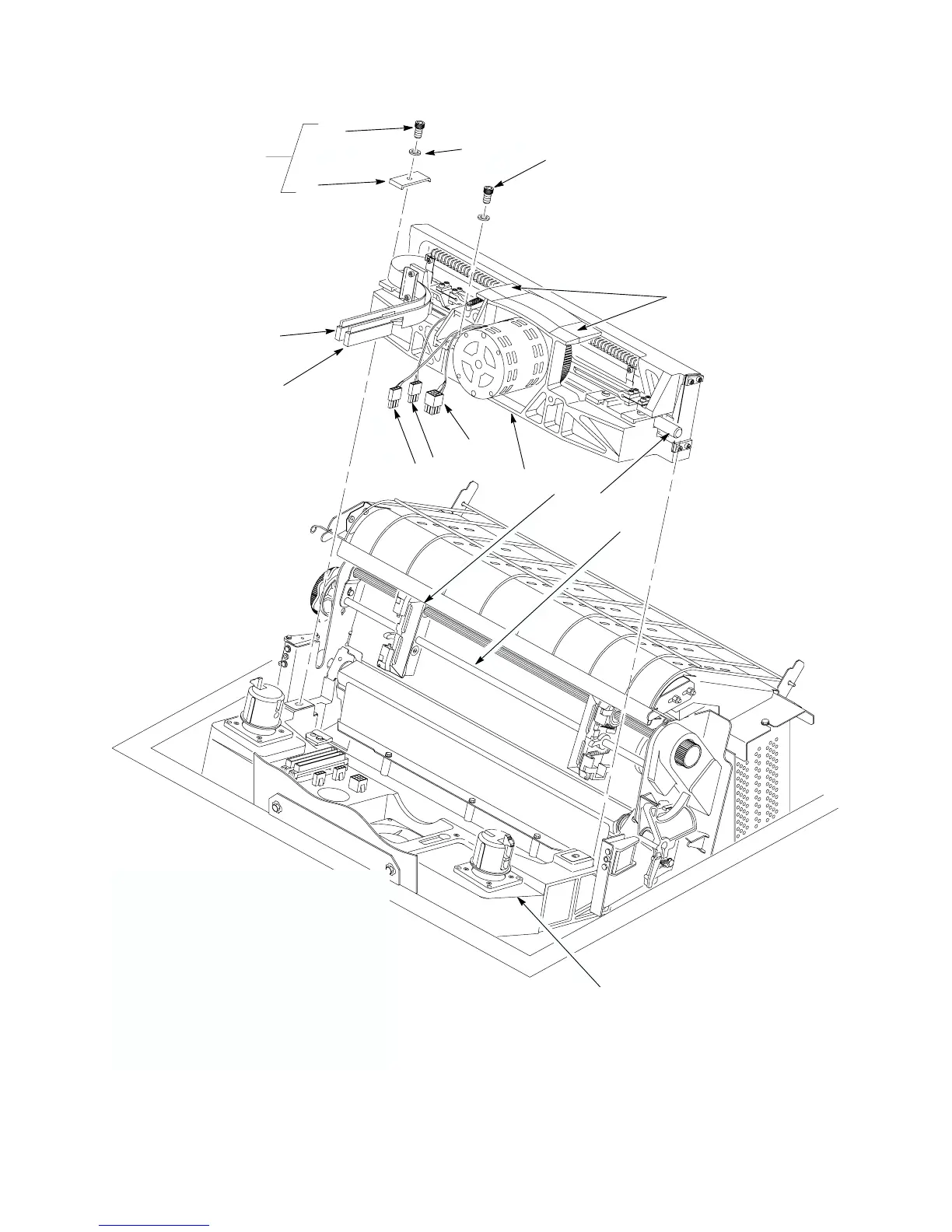
1. MPU
Cable Connector (Ref)
2.
Shuttle Motor Cable Connector (Ref)
3.
Shuttle Cable Assembly Connector (Ref)
4.
Left Flex Circuit Ribbon Connector (Ref)
5.
Right Flex Circuit Ribbon Connector (Ref)
6. Clamp Screw
, Side (2) (Skt cap, 10–24x.50)
7.
Side Clamp (2) (P/N 150399–001)
8.
Guide Shaft (p/o item 10.)
9. Center Screw
, Captive (p/o item 10.)
10.
Shuttle Frame Assembly (P/N 150181–901)
11.
Base Casting (P/N 150727–001)
12.
Outer Beam Standof
f (2) (p/o item 10.)
13. T
ractor (2) (Set, L/R, P/N 140716–003)
14. T
ractor Support Shaft (P/N 1
11685–001)
11
Flat #10
13
14
Figure 5–31 . Shuttle Frame Assembly Removal/Installation
 Loading...