6–28 Optional Equipment
Symptoms Not Indicated by Fault Messages
NOTE: Do not attempt field repairs on electronic components or assemblies
— replace the entire assembly with an operational spare. Most
electronic problems are corrected by replacing the printed circuit
board assembly (PCBA), sensor, or cable that causes the fault
indication.
The same is true of electro–mechanical failures traced to the shuttle
frame assembly or the hammer bank. Replace the entire assemblies;
they are not field repairable.
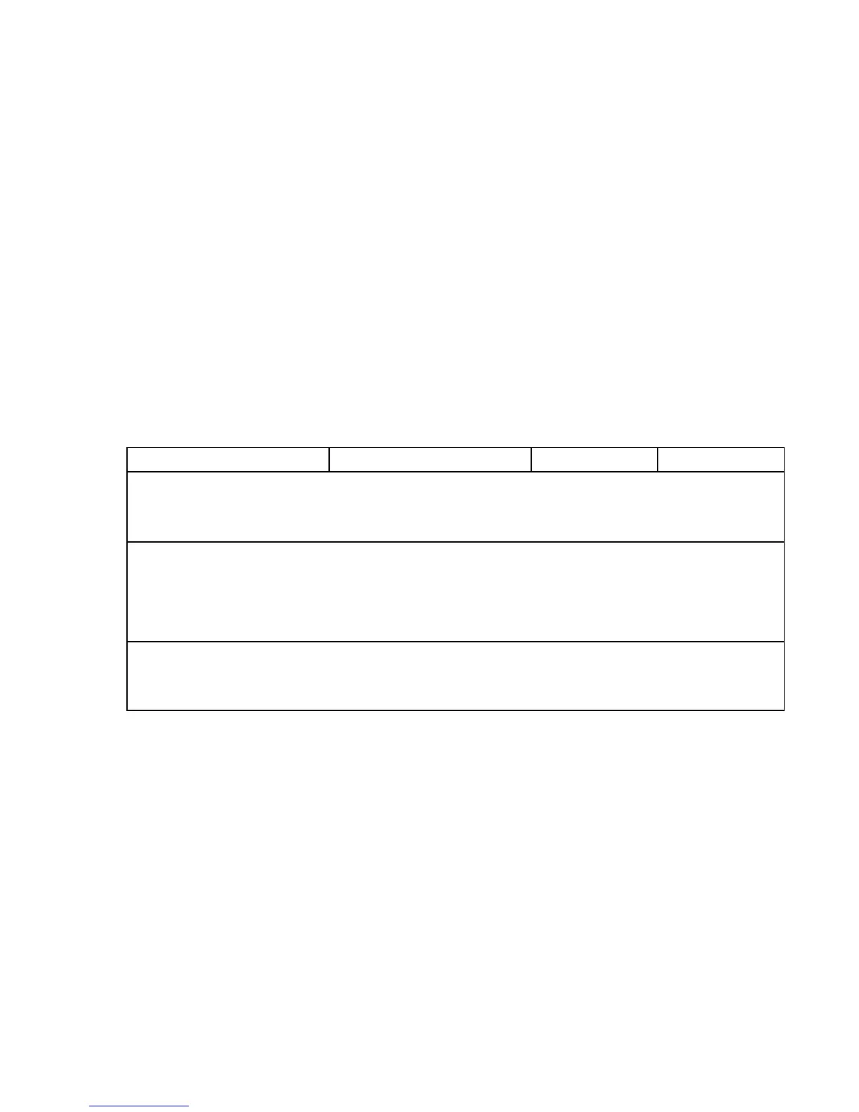
NO DISPLAY
Instruction Indication Yes No
1. Inspect control panel ribbon
cable connector for bent or
broken pins.
Pins
are damaged.
Straighten
bent
pins. If broken,
replace control
panel assembly.
Step 2.
2. Power up printer and check
display and card cage fan
operation.
Display
comes on.
Resume
printing.
Replace one at a
time: power
supply PCBA,
mech driver
PCBA. Test printer
operation.
3. Power up printer and check
display.
Display
comes on.
Resume
printing.
Replace the
control panel
assembly. Test
printer operation.
 Loading...