E–16 Principles of Operation
Shuttle Frame and Hammer Bank Assemblies
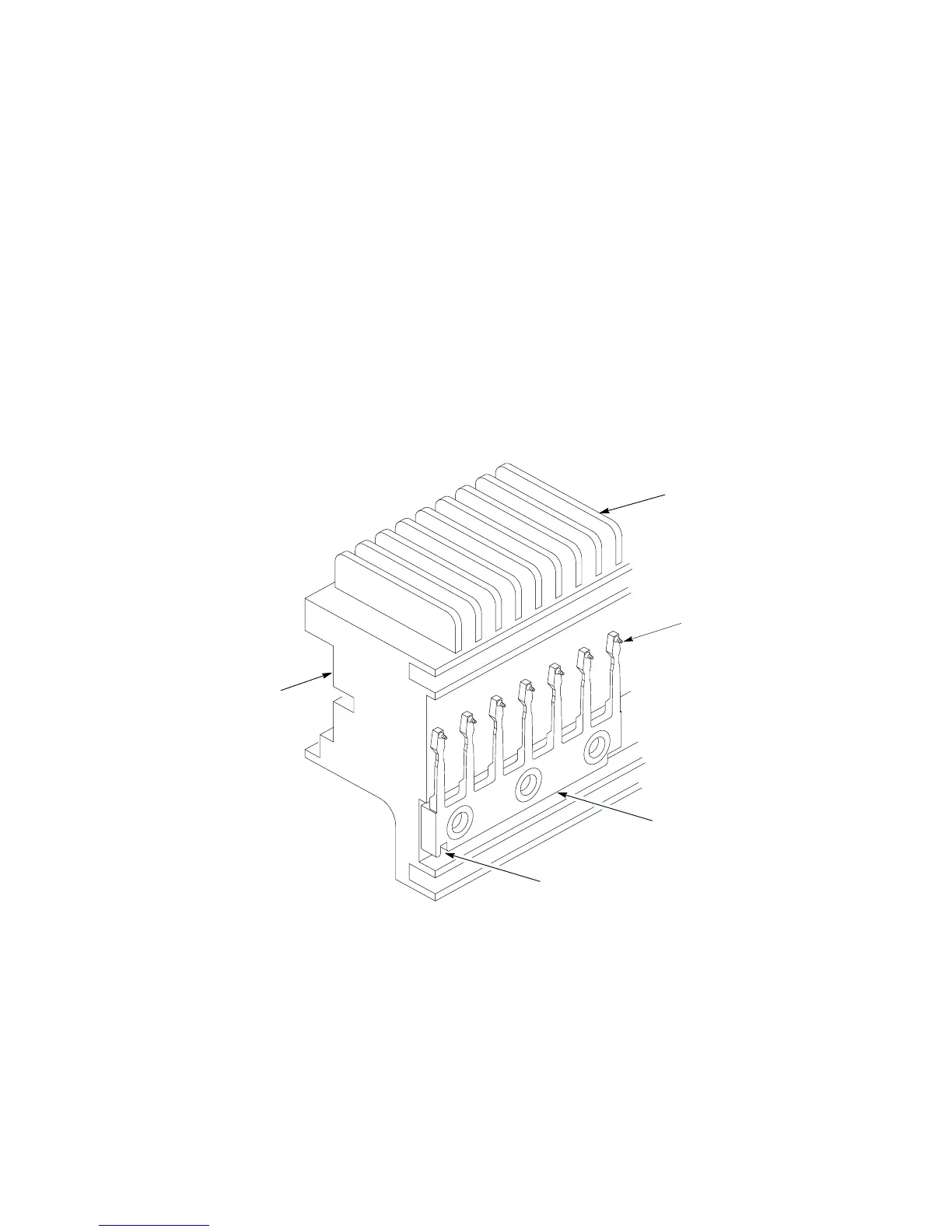
Dots are printed by 47 hammer springs mounted on the hammer bank. The
hammers are arrayed in seven comb–like hammer spring assemblies, or frets.
Each fret contains 7 hammers. Using 49 hammers balances the magnetic
field characteristics of the hammer bank, while design parameters determine
the use of 47 hammers for printing. (The first and 49th hammers do not
print.) The frets mount to the hammer bank on alignment pins, eliminating
the need for individual hammer alignment.
Each print hammer is a stiff leaf spring with a cylindrical, tungsten carbide
tip on the free end. (See Figure E–7.) A permanent magnet runs the length of
the hammer bank and acts on the hammer springs through individual pole
pieces. The pole pieces magnetically attract and hold the free end of the
hammer spring under tension. This is called the retracted state.
Hammer Bank:
Coils, Magnet,
and Pole Pieces
Alignment Pin
Hammer Spring
Assembly
Tungsten Carbide
Hammer Tip
Heat Sink
Figure E–7. Hammer Springs and Hammer Bank (Detail)
A pair of electromagnetic coils is mounted behind each hammer and wound
around each pole piece. The coils are normally de–energized. When hammer
driver logic determines that the hammer must print a dot, a current pulse
energizes the coils. The polarity of the resulting magnetic field opposes the
field of the permanent magnet, cancelling its effect and releasing the



 To Next Page