5–9Replacement Procedures
Card cage floor
Front
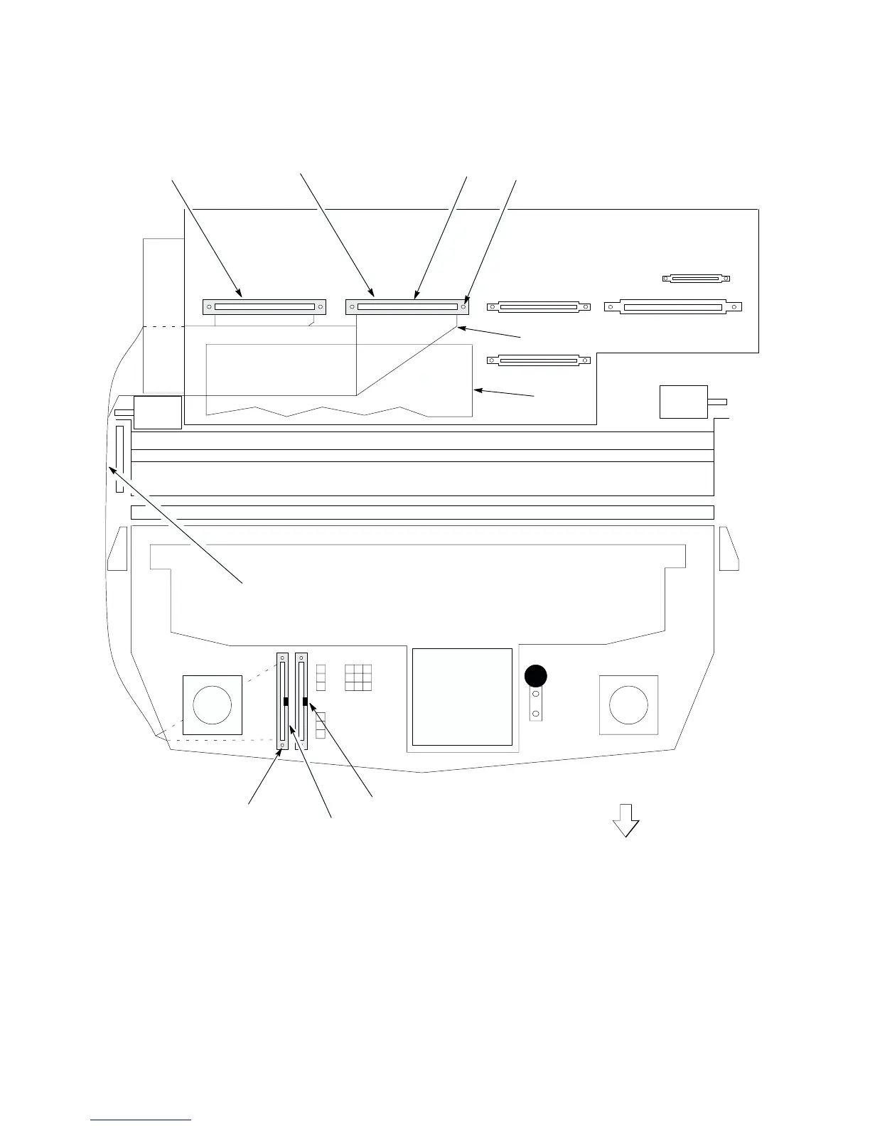
Printer viewed from above, PCBAs removed.
Shuttle Frame
Assembly
Hammer Bank
Fan
Card
Cage
Fan
Paper feed mechanisms
and barrier panel
Platen
Base casting
Platen
open
motor
Paper
feed
motor
1. Screw (2) (Scr, w/LW, 4–40x.75; and #4 flat washer
2. Connector (p/o item 5.)
3. Screw (2) (Same as item 1.)
4. Connector (p/o item 5.)
5. Hammer Bank Cable Assembly (P/N 150215–001)
6. Protective Barrier (Ref)
2
1
Right hammer bank
cable assembly
Left hammer bank
cable assembly
3
4
5
NOTE: Connector locating key is
on the right side of each
connector.
Tie wraps
6
Figure 5–3 . Cable Assembly, Hammer Bank, Removal/Installation