5.2 Control elements
11 13 15 161412
10
9
8
7
3
1
a)
b)
5
4
2
6
P_DE_0017_SW
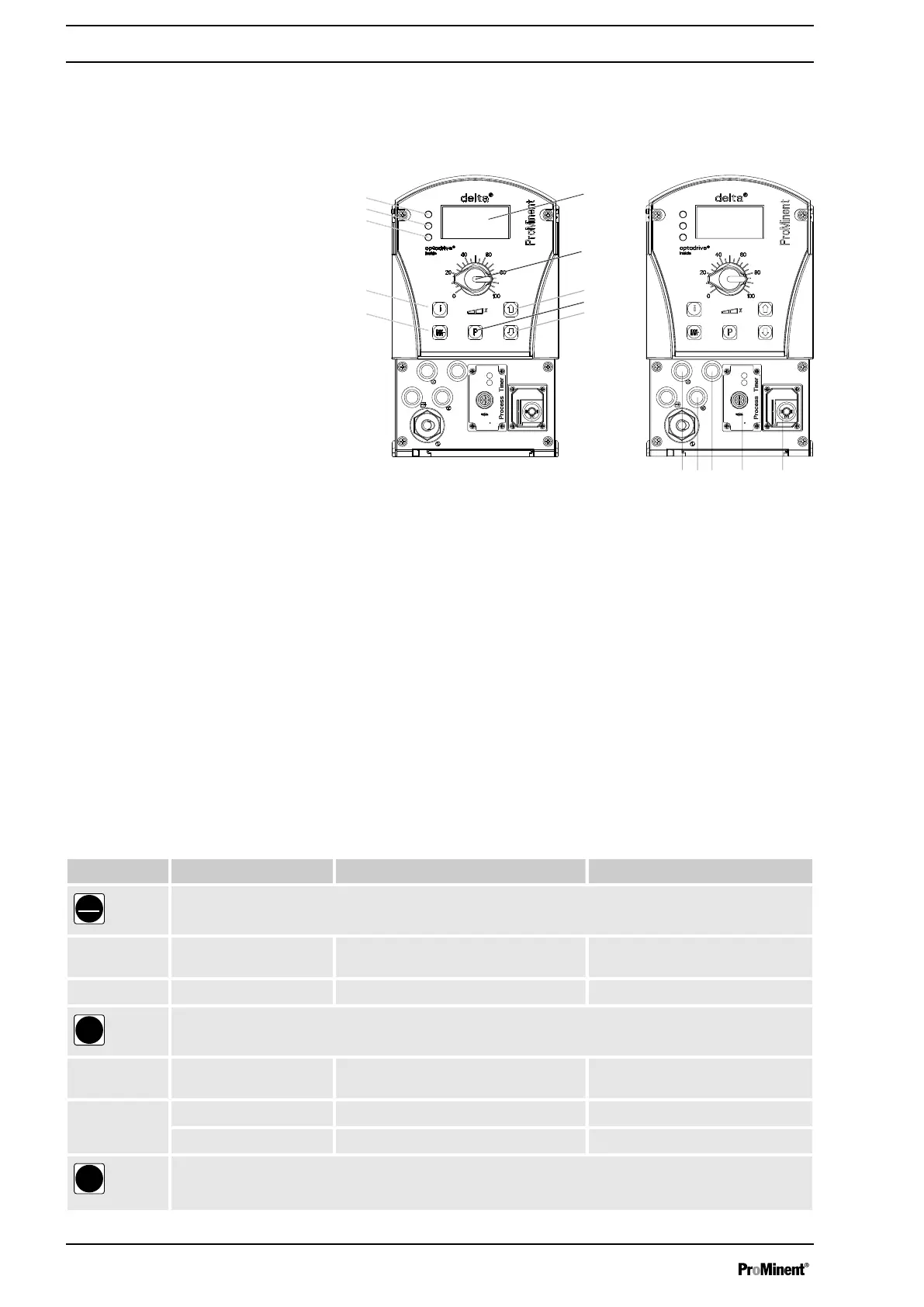
Fig. 4: a) Displays and keys, b) Electrical control connections
1 LCD display
2 Stroke length adjustment knob
3 Key
[UP]
4 Key
[P]
5 Key
[DOWN]
6 Key
[STOP/START]
7 Key
[i]
8 Operating indicator (green)
9 Warning indicator (yellow)
10 Fault indicator (red)
11 "External control" jack
12 "Dosing monitor" jack
13 "Level Switch" jack
14 "Diaphragm rupture reporter" jack
15
Optional module slot (timer, PROFIBUS
®
, CAN-Bus)
16 Relay and mA-output (option)
5.2.1 Key functions
Key Application In continuous displays (operation) In adjustment mode (set up)
[STOP/
START]
Pressed briefly Stop pump, Stop pump,
start pump start pump
[P]
Pressed briefly Start batch (only in
‘ Batch’
operating
mode), acknowledge fault
Confirm entry - jump to next menu
point or to continuous display
Pressed for 2 s Change to adjustment mode -
Pressed for 3 s - Jump to continuous display
Device overview and control elements
16
 Loading...