The pump performs one or more strokes if:
n Pin 2 and pin 4 are connected to each other for at least 20 ms. At the
same time, pin 1 and pin 4 must also be connected to each other.
The pump works at a pre-set stroke rate if:
n Pin 5 and pin 4 are connected to each other. At the same time, pin 1
and pin 4 must also be connected to each other. The auxiliary fre‐
quency is factory-preset to the maximum stroke rate.
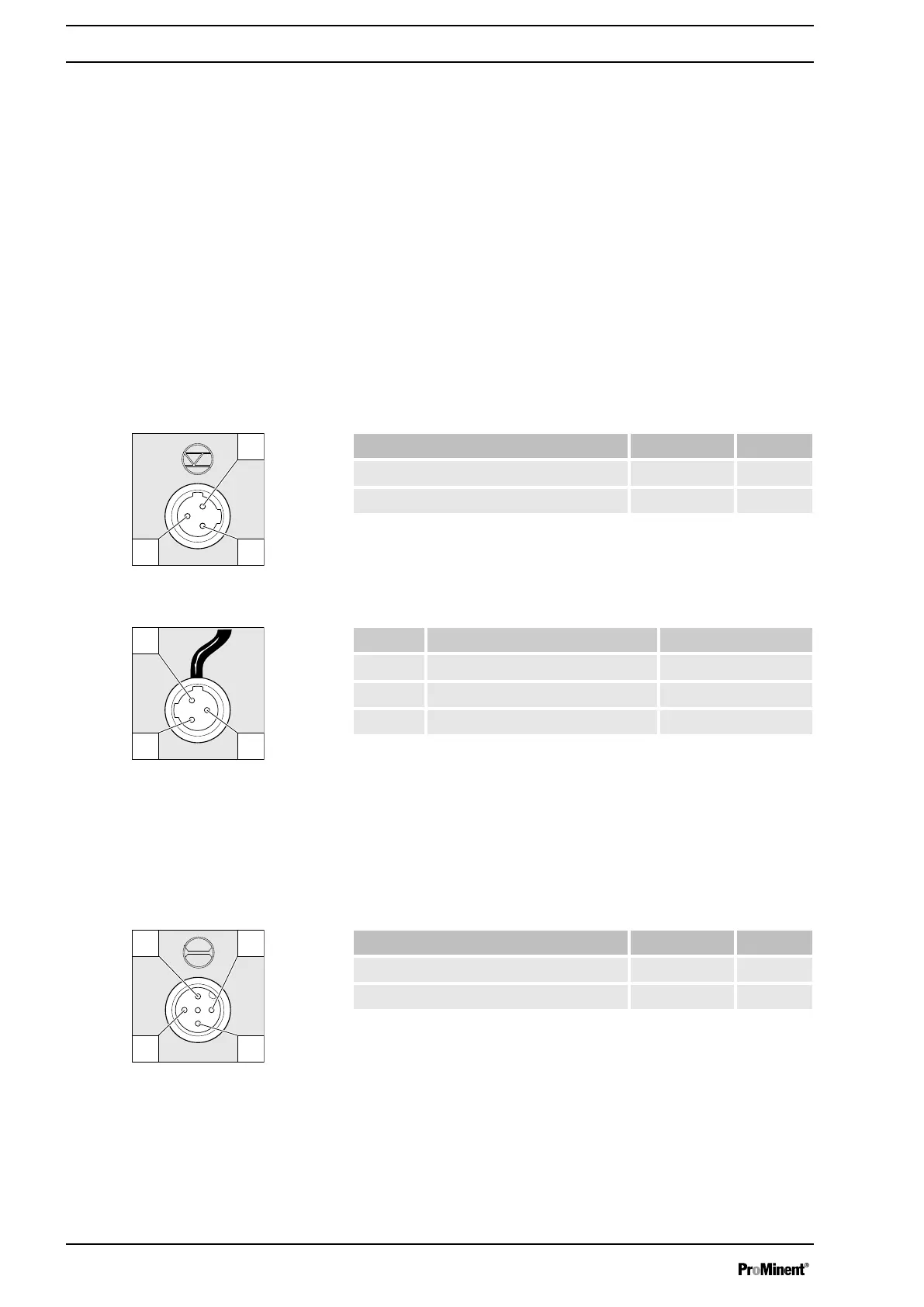
9.2.2 "Level Switch" terminal
There is a connecting option for a 2-stage level switch with pre-warning
and limit stop.
Electrical interface
Data Value Unit
Voltage with open contacts 5 V
Input resistance 10 kΩ
Control via:
n potential-free contact (load: 0.5 mA at 5 V) or
n Semiconductor switch (residual voltage < 0.7 V)
Pin Function 3-conductor cable
1 Earth / GND black
2 Minimum pre-warning blue
3 Minimum limit stop brown
9.2.3 "Dosing monitor" terminal
There is a connecting option for a dosing monitor.
Electrical interface
Data Value Unit
Voltage with open contacts 5 V
Input resistance 10 kΩ
Control via:
n potential-free contact (load: 0.5 mA at 5 V) or
"External contact" operating mode
"Auxiliary frequency" operating mode
Fig. 12: Pump pin assignments
Fig. 13: Cable conductor assignments
Fig. 14: Pump pin assignments
Electrical installation
34