9.2 Description of the sockets
9.2.1
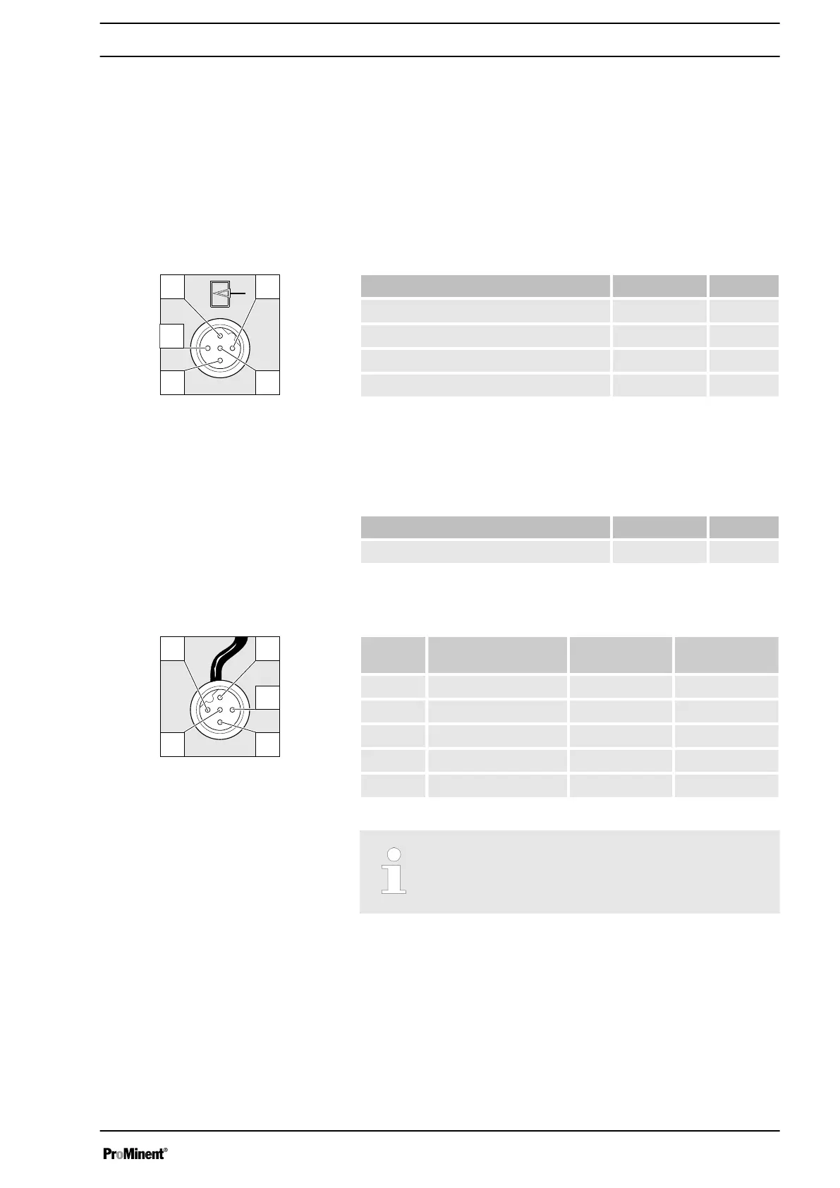
"External control" terminal
The "external control" socket is a five-pin panel jack. It is compatible with
two- and four-conductor cables.
Only use a five-pin cable with the "Auxiliary frequency" and "mA-input"
functions.
Electrical interface for pin 1 "Pause" - pin 2 "External contact" - pin 5 "Aux‐
iliary frequency"
Data Value Unit
Voltage with open contacts 5 V
Input resistance 10 kΩ
Max. pulse frequency 25 pulse/s
Minimum pulse duration 20 ms
Control via:
n potential-free contact (load: 0.5 mA at 5 V) or
n Semiconductor switch (residual voltage < 0.7 V)
Electrical interface for pin 3 "mA input" (with identity code characteristic
"Control variant": 3, 5 and R)
1
Data Value Unit
Input apparent ohmic resistance, approx. 120 Ω
1
The metering pump makes its first metering stroke at approx. 0.4 mA (4.4
mA) and starts continuous operation at approx. 19.2 mA.
Pin Function 5-conductor
cable
2-conductor
cable
1 Pause brown bridged at pin 4
2 External contact white brown
3 mA input* blue -
4 Earth / GND black white
5 Auxiliary frequency grey -
* with identity code characteristic "Control version": 3, 5 and R
Refer to the functional description for the hierarchy of func‐
tions and operating modes.
The pump does not work if:
n the cable is connected and pin 1 and pin 4 are open.
The pump works if:
n the cable is connected and pin 1 and pin 4 are connected.
n no cable is connected.
Fig. 10: Pump pin assignments
Fig. 11: Cable conductor assignments
"Pause" function
Electrical installation
33