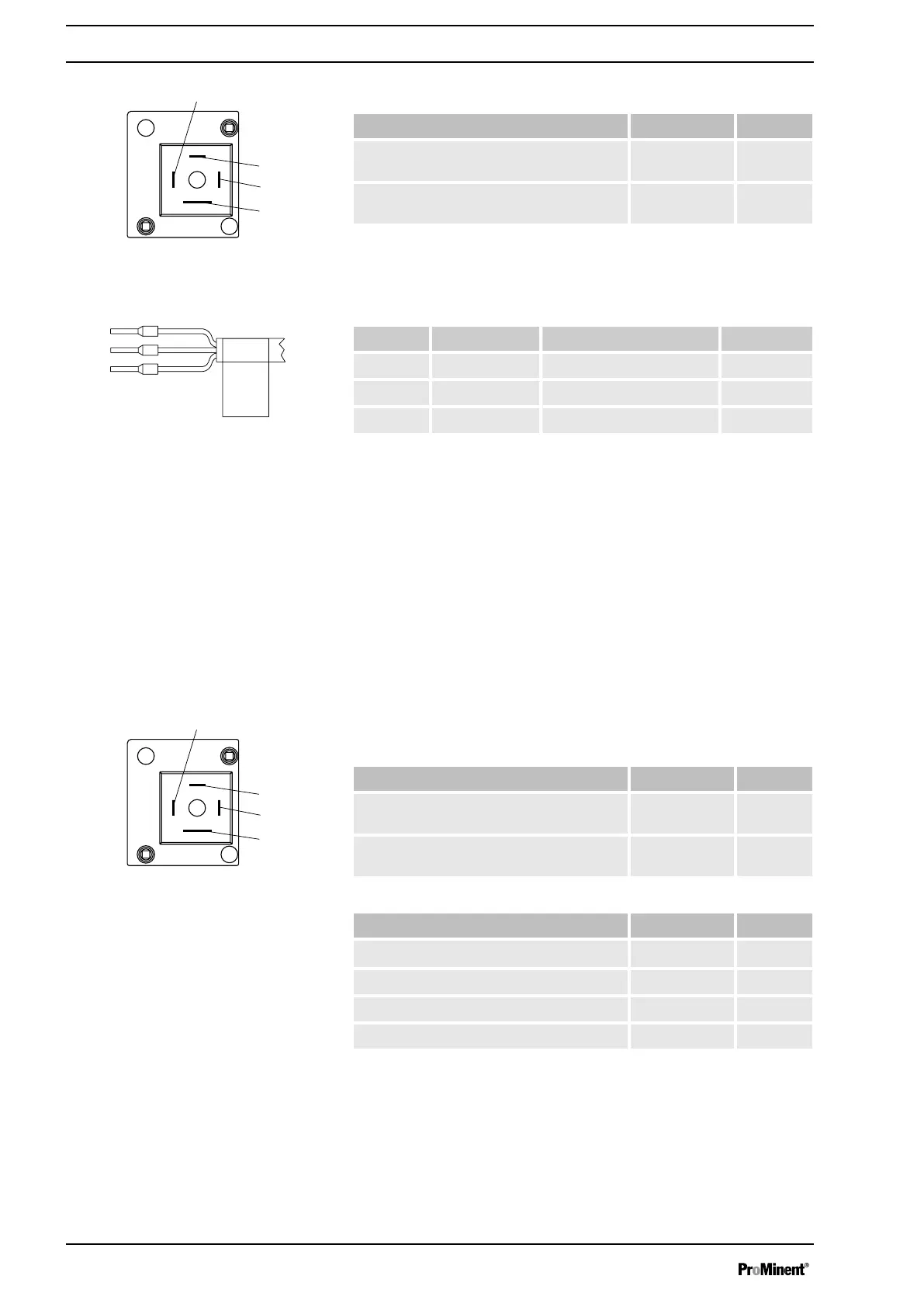
Electrical interface
Data Value Unit
Maximum contact load at 230 V and 50/60
Hz:
8 A
Minimum mechanical lifespan: 200 000 Switching
operations
To pin VDE cable Contact CSA cable
1 white NO (normally open) white
2 green NC (normally closed) red
4 brown C (common) black
9.3.2 Output for other relays (identity code 4 + 5, 8 + 9, A + B)
A fault indicating and a pacing relay can optionally be ordered - refer to
ordering information in the appendix. The pacing output is electrically-iso‐
lated by means of an optocoupler with a semiconductor switch. The
second switch is a relay.
The behaviour is programmed ex factory. If another switching function is
required, the pump can be reprogrammed in the
‘Relay’
menu.
The fault indicating/pacing relay can be retrofitted and is operational once
attached to the relay board - refer to "Retrofitting Relays" supplementary
operating instructions.
Electrical interface
for fault indicating relay output:
Data Value Unit
Maximum contact load at 24 V and 50/60
Hz:
2 A
Minimum mechanical lifespan: 20,000,000 Switching
operations
for semiconductor switch pacing relay:
Data Value Unit
Residual voltage max. at I
off max
= 1 µA 0.4 V
Maximum current 100 mA
Maximum voltage 24 VDC
Pacing pulse duration, approx. 100 ms
Fig. 18: Pump pin assignments
Identity code 1 + 3 or 6 + 7
Fig. 19: Cable conductor assignments
Fig. 20: Pump pin assignments
Electrical installation
36



 To Next Page