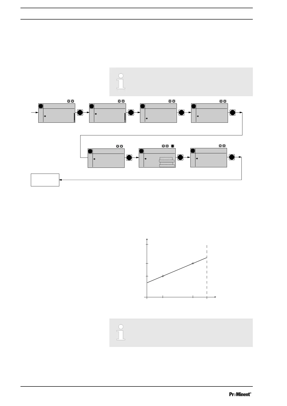
In the processing type
‘Curve’
you can freely program the pump behav‐
iour.
There are three options:
n Linear
n Lower sideband
n Upper sideband
The following applies to all three options:
The smallest processable difference between I1 and I2 is 4
mA (ll I1-I2 ll ≥4 mA).
PP
P
P
P
P
P
P
P
Analog
Analog
0..20mA
4..20mA
Curve
P
Settings
Analog
Analog
Concentration
Auxiliary
Calibration
P
Main menu
Analog
Mode
Settings
Security
Clear
P
Curve
Analog
Line
Upper Sideband
bottom sideband
0..20
0..20
0..20
0..20
P
Upper Sideband
Analog
I1= 04.0mA
F1= 060 H/h
I2= 20.0mA
F2= 100 H/h
P
Upper Sideband
Analog
I1= 04.0mA
F1= 060 H/h
I2= 20.0mA
F2= 100 H/h
P
Upper Sideband
Analog
Alarm message: On
0..20
0..20
0..20
Continuous
display
Linear
The "Linear" symbol appears in the LCD display. You can enter any stroke
rate- behaviour of the pump proportional to the current signal. For this pur‐
pose, enter any two points P1 (I1, F1) and P2 (I2, F2) (F1 is the stroke rate
at which the pump is to operate at current I1, F2 is the stroke rate at which
the pump is to operate at current I2...); this defines a straight line and thus
the behaviour is specified:
I [mA]
I 1
I 2
F1
F2
Fmax
0 20
P1
P2
B0088
Fig. 25: Rate(frequency)-Current Diagram for Linear control
Plot a diagram similar to the one above - with values for (I1,
F1) and (I2, F2) – so that you can set the pump as desired!
Under the menu option
‘Alarm message’
(error) you can activate an error
processing sequence for the
‘Curve’
processing type. For current signals
below 3.8 mA, an error message appears and the pump stops.
Curve
Error processing
Set up
46



 To Next Page