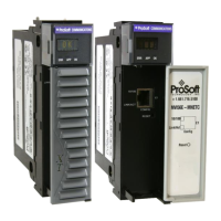
MVI56E-MNETC/MNETCXT ♦ ControlLogix Platform Reference
Modbus TCP/IP Client Enhanced Communication Module - Client/Server User Manual
ProSoft Technology, Inc. Page 103 of 172
September 20, 2018
Standard 1756 ControlLogix
®
single-slot module
800 mA @ 5 VDC
3 mA @ 24 VDC
0°C to 60°C (32°F to 140°F)
-25°C to 70°C (-13°F to 140°F) - MVI56E-MNETCXT
-40°C to 85°C (-40°F to 185°F)
Extreme/Harsh Environment
MVI56E-MNETXT comes with conformal coating
30 g operational
50 g non-operational
5% to 95% (with no condensation)
Battery Status (ERR)
Application Status (APP)
Module Status (OK)
4-character, scrolling,
alphanumeric LED display
Shows module, version, IP, application port setting, port
status, and error information
10/100 Base-T, RJ45 Connector, for CAT5 cable
Link and Activity LED indicators
Auto-crossover cable detection
5.2 Functional Overview
5.2.1 Backplane Data Transfer
The MVI56E-MNETC/MNETCXT module communicates directly over the
ControlLogix backplane. Data is paged between the module and the ControlLogix
processor across the backplane using the module's input and output images. The
update frequency of the images is determined by the scheduled scan rate
defined by the user for the module and the communication load on the module.
Typical update times range from 1 to 10 milliseconds.
This bi-directional transfer of data is accomplished by the module putting data in
the input image to send to the processor. Data in the input image is placed in the
processor's controller tags by ladder logic. The input image is set to 250 words.
Processor logic inserts data to the output image to be transferred to the module.
The module's firmware program extracts the data and places it in the module's
internal database. The output image is set to 248 words.

 Loading...