MVI56E-MNETC/MNETCXT ♦ ControlLogix Platform MVI56E-MNETC/MNETCXT Configuration
Modbus TCP/IP Client Enhanced Communication Module - Client/Server User Manual
ProSoft Technology, Inc. Page 65 of 172
September 20, 2018
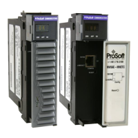
2.2.3 Connecting Your PC to the Module's Ethernet Port
With the module securely mounted, connect one end of the Ethernet cable to the
Config (E1) Port, and the other end to an Ethernet hub or switch accessible from
the same network as your PC. You can also connect directly from the Ethernet
Port on your PC to the Config (E1) Port on the module by using an Ethernet
crossover cable (not included).
Setting Up a Temporary IP Address
Important: ProSoft Configuration Builder locates MVI56E-MNETC/MNETCXT modules through
UDP broadcast messages. These messages may be blocked by routers or layer 3 switches. In that
case, ProSoft Discovery Service will be unable to locate the modules.
To use ProSoft Configuration Builder, arrange the Ethernet connection so that there is no router/
layer 3 switch between the computer and the module OR reconfigure the router/ layer 3 switch to
allow routing of the UDP broadcast messages.
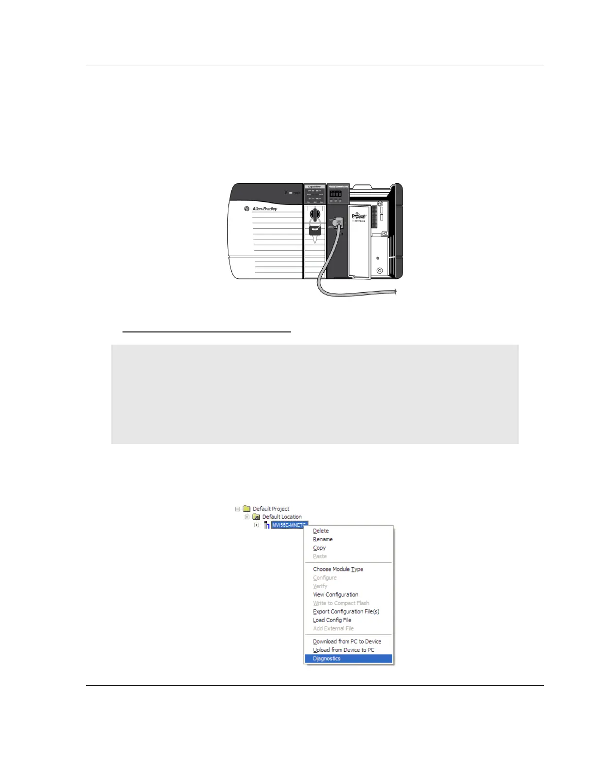
1 In the tree view in ProSoft Configuration Builder, right-click the MVI56E-
MNETC/MNETCXT icon to open a shortcut menu.
2 On the shortcut menu, choose DIAGNOSTICS.