MVI56E-MCMR ♦ ControlLogix Platform Reference
Modbus Communication Module with Reduced Data Block User Manual
ProSoft Technology, Inc. Page 155 of 223
Block Request from Processor to Module
Enable (must be set to 1)
Internal DB Address (0-4999)
Count (1-125, or maximum supported by the target Slave device)
Device (Modbus Slave Device Address Number of target Slave)
Function (Modbus Function Code: 1, 2, 3, 4, 5, 6, 15, or 16)
Device Address (0-9999, address offset in target Slave database)
Refer to Master Command Configuration (page 57) for a detailed definition of the
fields contained in this block. They are the same as those used in constructing
the commands in ProSoft Configuration Builder (PCB) in the MODBUS PORT 1
COMMANDS or MODBUS PORT 2 COMMANDS lists.
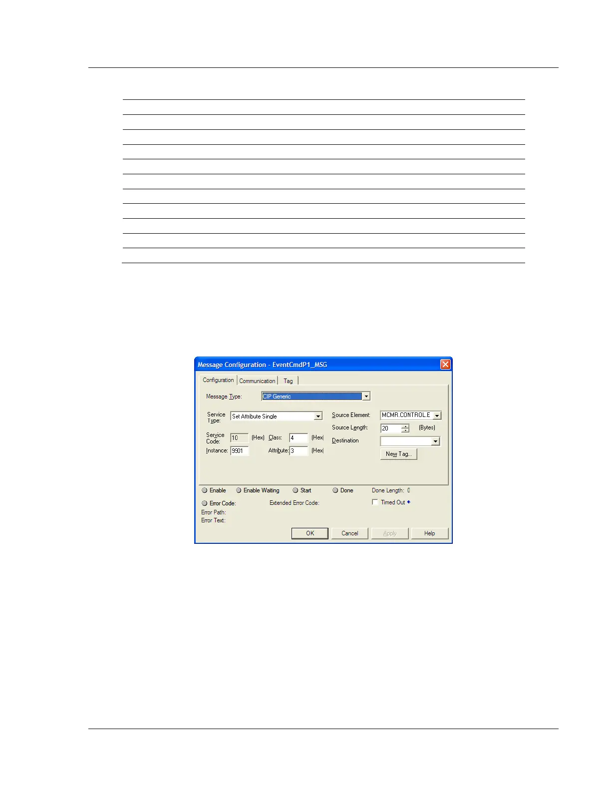
The Send Event Command message uses the following parameters in the MSG
configuration: