MVI56E-MCMR ♦ ControlLogix Platform Start Here
Modbus Communication Module with Reduced Data Block User Manual
ProSoft Technology, Inc. Page 37 of 223
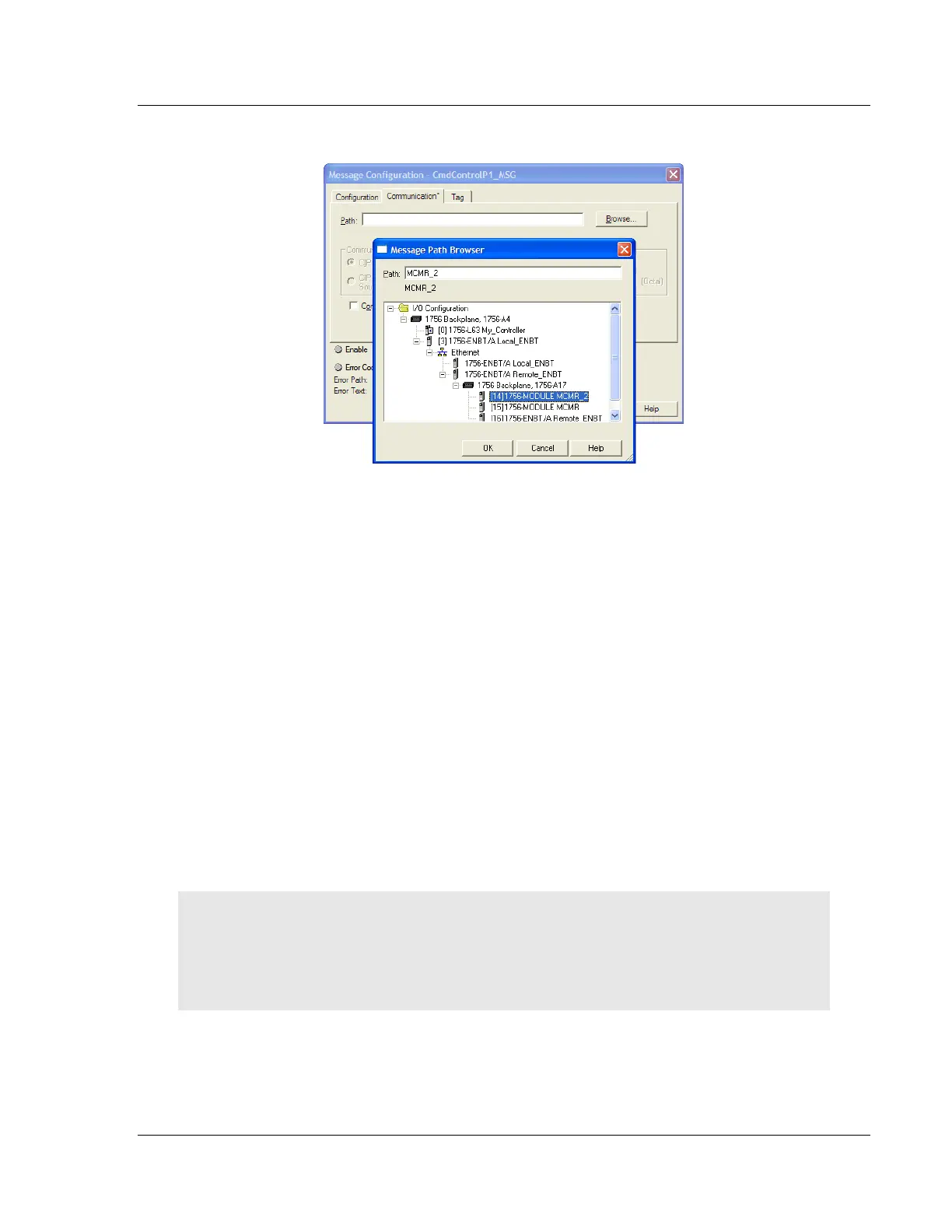
3 Select the module to configure the message path.
4 Repeat these steps for each MSG tag, and for each additional MVI56E-
MCMR module.
The setup procedure is now complete. Save the project and download the
application to your ControlLogix processor.
1.8.5 Adjusting the Input and Output Array Sizes
The module internal database is divided into two user-configurable areas:
Read Data
Write Data
The Read Data area is moved from the module to the processor, while the Write
Data area is moved from the processor to the module. You can configure the
start register and size of each area. The size of each area you configure must
match the Add-On instruction controller tag array sizes for the READDATA and
WRITEDATA arrays.
The MVI56E-MCMR sample program is configured for 600 registers of
READDATA and 600 registers of WRITEDATA, which is sufficient for most
applications. This topic describes how to configure user data for applications
requiring more than 600 registers of ReadData and WriteData.
Important: Because the module pages data in blocks of 40 registers at a time, you must configure
your user data in multiples of 40 registers.
Caution: When you change the array size, RSLogix may reset the MCMR tag values to zero. To
avoid data loss, be sure to save your settings before continuing.