Configuring the MVI56E-MCMR Module MVI56E-MCMR ♦ ControlLogix Platform
User Manual Modbus Communication Module with Reduced Data Block
Page 52 of 223 ProSoft Technology, Inc.
2.3 Configuration as a Modbus Master
2.3.1 Overview
This section describes how to configure the module as a MODBUS MASTER
device. The Master is the only device on a Modbus network that can initiate
communications. A Master device issues a request message, and then waits for
the slave to respond. When the slave responds, or when a timeout has occurred,
the Modbus Master will then execute the next command in the list.
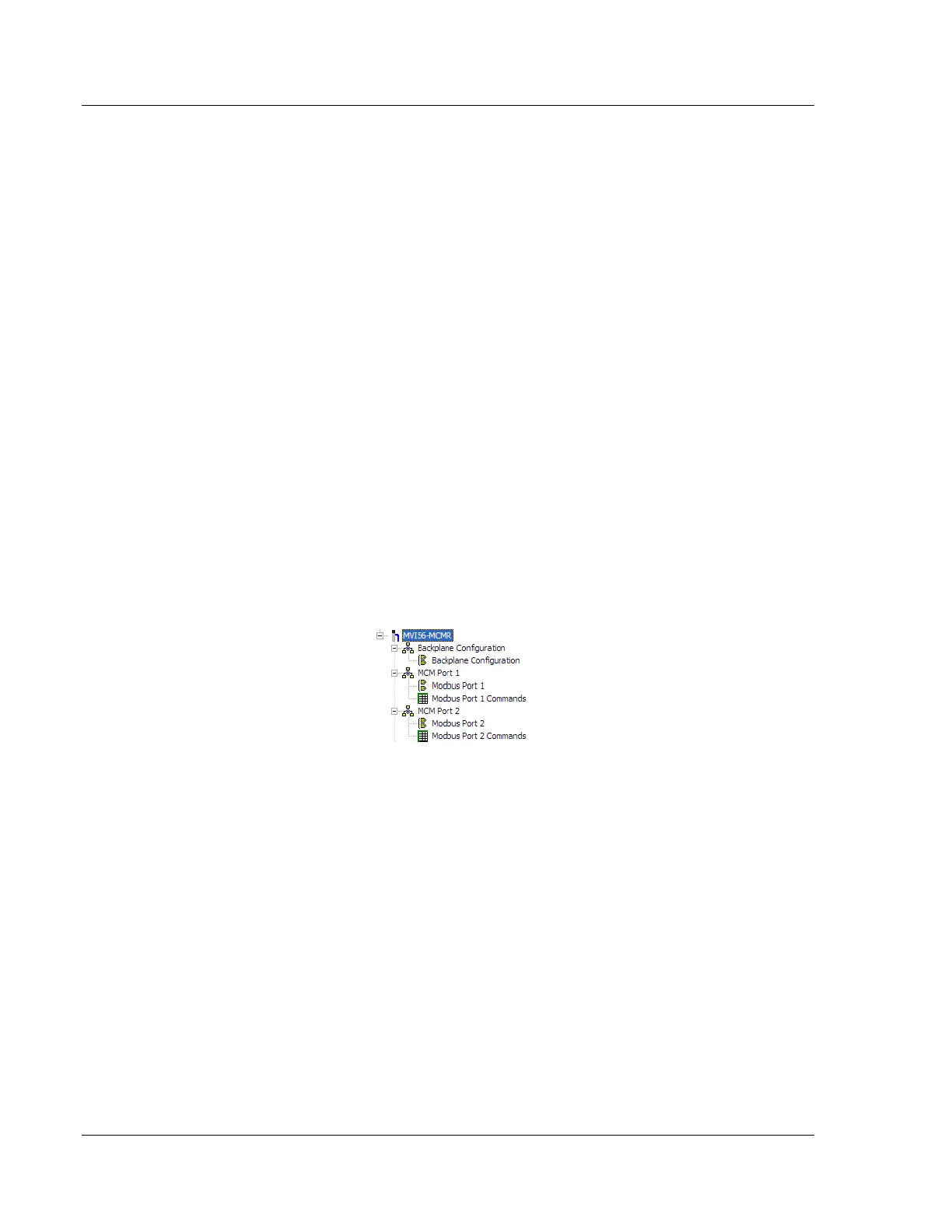
The following ProSoft Configuration Builder sections contain the Modbus Master
configuration. You must configure all three sections.
1 The BACKPLANE CONFIGURATION section sets up the backplane
communication between the MVI56E-MCMR module and the ControlLogix
processor (page 53). These settings include register addresses for ReadData
and WriteData. You can configure up to 5000 data registers in the module to
exchange data with the ControlLogix processor.
2 The MODBUS PORT1 and MODBUS PORT 2 sections configure the Modbus
application serial ports (page 54). These sections configure parameters such
as baud rate, parity, data bits, stop bits, and command response timeout.
3 The MODBUS PORT 1 COMMANDS and MODBUS PORT 2 COMMANDS sections
define a polling table (command list) for the Modbus Master (page 57). These
sections contain the addresses for devices on the network, the types of data
(Modbus Function Codes) to read from and write to those devices, and the
location to store the data within the module’s 5000 data registers.