Configuring the MVI56E-MCMR Module MVI56E-MCMR ♦ ControlLogix Platform
User Manual Modbus Communication Module with Reduced Data Block
Page 74 of 223 ProSoft Technology, Inc.
Write Floats to Slave Device
To issue a Write command to Floating-Point addresses, use the configuration in
the following table. The table describes the Modbus Map for the slave device.
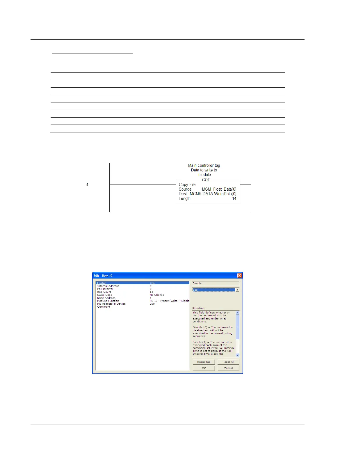
You must use a COP statement to copy the data from floating-point data tags
within the ControlLogix processor, into the MCMR.DATA.WRITEDATA array used
by the MVI56E-MCMR module. Below is an example.
The length of this COP statement must now be 14. This will COP as many of the
MCM_FLOAT_DATA values required to occupy the MCMR.DATA.WRITEDATA
array for a length of 14. This will take 7 registers, MCM_FLOAT_DATA[0] TO [6],
and place that data into MCMR.DATA.WRITEDATA[0] TO [13].
You must configure the command to write all 7 floats (14 Modbus addresses) as
follows.
The above command will take the data from MCMR.DATA.WRITEDATA[0] TO [13]
and write this information to Modbus Slave Device Address 1 at data addresses
40261 to 40274.