MVI56E-MCMR ♦ ControlLogix Platform Configuring the MVI56E-MCMR Module
Modbus Communication Module with Reduced Data Block User Manual
ProSoft Technology, Inc. Page 91 of 223
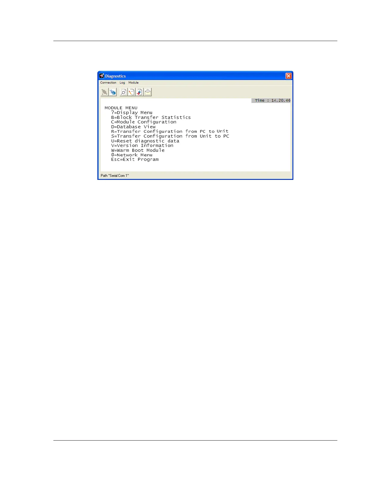
7 If the Test Connection is successful, click CONNECT. The Diagnostics menu
will display in the Diagnostics window.