10
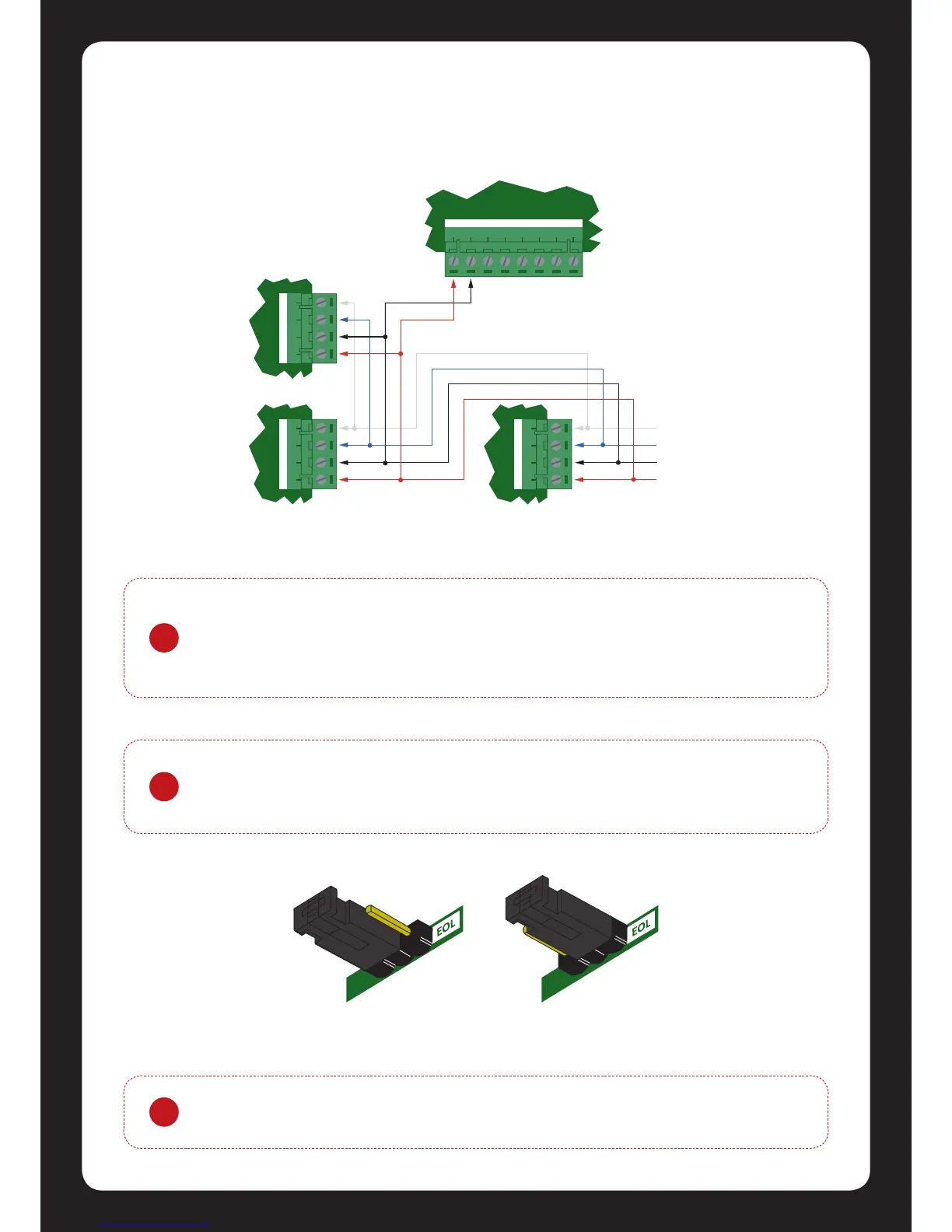
Figure 10 - EOL Jumper
Always connect the Protégé® SE Integrated System Controllers NA and NB terminals to the NA and
NB terminals of the expansion devices and keypads. The N+ and N- must go to a 12V power supply
source as shown in gure 9 below.
Figure 9 - Network Power Connecon
?
The diagram above shows a power connecon taken from the Auxiliary Power
Outputs on the Protégé® SE Integrated System Controller’s zone terminals. It is
recommended to only use this connecon for smaller systems where limited power
is required. For larger installaons use a separate power supply.
NAN+ N- NB
NAN+ N- NB
NAN+ N- NB
+AUX-Z13 COMCOMZ14Z15 Z16
Protégé® SE Integrated System
Controller or module supplying
power to networke d devices
AUX power from Module or
external power supply
Next modules
on network
?
The EOL (End Of Line) jumper seng must be set in the on posion for the rst and
last expansion device only.
!
The 12V N+ and N- Communicaon Input must be supplied from only one point.
Connecons from more than one 12V supply may cause failure or damage to the
units supplying power.