19
!
The zones 9-12 and 13-16 can operate as either general purpose zone inputs or as
onboard reader inputs. If used as general purpose zone inputs then make sure that
these input are not dened in the onboard reader set up. Please refer to the table
on page 16 for the default sengs of these zones.
6.0 Inputs
6.1 Zones
The Protégé® SE Integrated System Controller has 16 Zone Inputs. The Protégé® SE Integrated
System Controller also monitors 64 trouble zones used to report trouble condions. A trouble zone
represents a trouble condion within the system. The trouble zone will open or go in to alarm
when that trouble condion is present, and close or return to normal when the trouble condion
restores. As an example trouble zone CP001:01 will open or go in to alarm when the tamper input
on the Protégé® SE Integrated System Controller is open.
The Protégé® SE Integrated System Controller can monitor and control thousands of zone and
trouble zone inputs by using the expansion modules.
The Protégé® SE Integrated System Controller can monitor the state of up to 16 zone inputs such as
magnec contacts, moon detectors and temperature sensors. Devices connected to these zones
can be installed to a maximum distance of 300m (1000) from the Protégé® SE Integrated System
Controller when using 22 AWG. The Protégé® SE Integrated System Controller supports normally
opened and normally closed conguraons with or without EOL resistors.
Zones can be programmed from the Protégé® Alphanumeric LCD Keypad (PRT-KLCD) or using the
Protégé® System Management Suite applicaon (PRT-SMGT). CP001:01 to CP001:16 represent
Zone 1 to Zone 16 on the Protégé® SE Integrated System Controller.
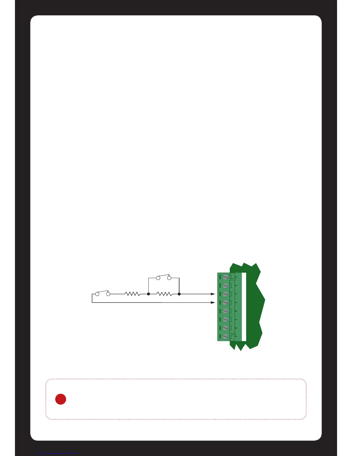
When using a zone with the EOL resistor conguraon, the Protégé® SE Integrated System
Controller generates an alarm condion when the state of a zone is toggled and generates a
tamper alarm condion when a wire fault (short circuit) or a cut (tampered) in the line occurs.
Zones default to require the EOL resistor conguraon.
Figure 21 - EOL Resistor Zone Conguraon