17
5.4 Lock Output Connecon
The Protégé® SE Integrated System Controller provides a connecon for 2x electric strike locks with
full monitoring of the lock circuit for tamper and over current/fuse blown condions. The door lock
monitoring can be disabled if it is not required.
?
When using a door with an Entry and Exit Reader, the lock output should be
connected to Bell 1, and enable the swap lock opon for the second reader input to
allow the reader LED’s to display the correct status.
!
Exceeding the maximum current on the controller outputs is not recommended.
Ensure the devices connected to the outputs are within the limits as detailed in the
Technical Specicaons secon on page 31.
!
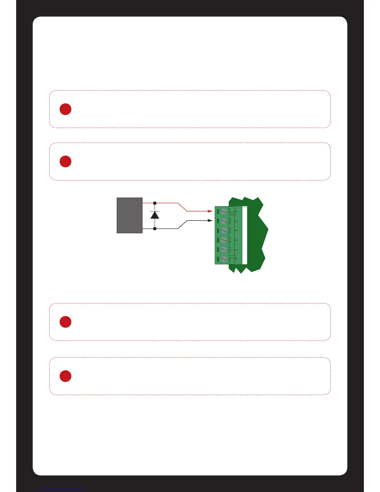
As indicated in gure 19 the Lock Outputs are shared with the Bell/Siren funcons.
You are able to select another output for the Lock Control (P3 or P4) if the
Bell/Siren funcon is required.
!
To use the lock outputs in conjuncon with the Onboard Reader module the Lock
PGM for the Door associated with the Reader Port must be congured to be the
desired Lock Output on the Controller. By default this is not congured.
Figure 19 - Lock Output Connecon