22
7.0 Programmable Outputs
The Protégé® SE Integrated System Controller has 8x Programmable Outputs (PGM’s). The PGM’s
are used to acvate sirens, bells, warning devices, control lighng and doors. The rst 2 PGM’s on
the Protégé® SE Integrated System Controller have special hardware designs that allows them to
monitor for fault condions and are ideally suited to driving sirens and warning devices.
7.1 Bell/Siren PGM Outputs
The + and - terminals of Bell 1 (PGM1 CP001:01) and Bell 2 (PGM2 CP001:02) are used to power
bells, sirens or any devices that require a steady voltage output. The Bell Outputs supply 12VDC
upon alarm and support one 20-wa siren. The Bell Output uses a electronically fused circuit and
automacally shuts down under fault condions.
If the load on the bell terminals returns to normal, the Protégé® SE Integrated System Controller
reinstates power to the bell terminals on the next transion of the output.
?
When the Bell Output is not used, the appropriate trouble zone will be acvated
(refer to the Trouble Zones secon on page 21). To avoid this, connect a 1K resistor
(provided in the accessory bag) across the Bell Output. If the bell is not being used
for another funcon, and the trouble zone is not programmed in the system, no
resistor is required.
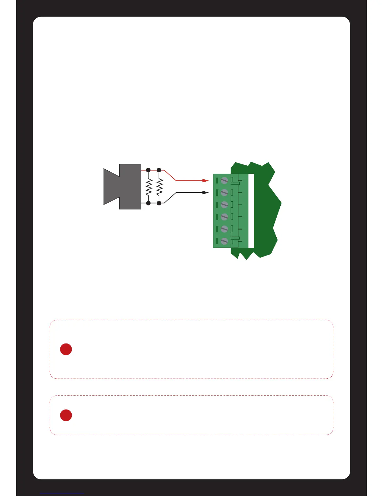
Figure 23 - Bell Siren PGM 1/2 Connecon
!
Connecng a Piezo Siren may result in a dull noise being emied. This is caused by
residual current from the monitoring circuit. Connect 2x 1K resistors in parallel to
prevent this from occurring.