141
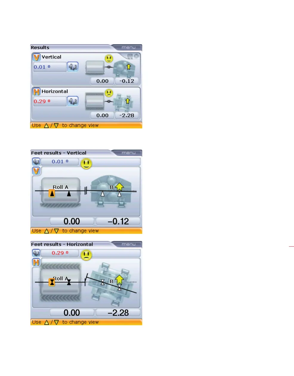
2. Cycle through the feet results using k/f/g.
3. If the machines are out of tolerance, reposition them with the help of the Move
function (refer to sections 5.13.3 – 5.13.5).
4. Remeasure to determine the new alignment condition.
Note that the angularity
is displayed in degrees
or mrad depending on
the ‘Angle format units’
selected under ‘Shaft
settings’ in the ‘Con-
figuration’ menu (refer to
section 8.2.7).
If a specific amount
of offset between the
machine shafts was
desired and the laser
holder assembly was set
up to this precise offset
as described in step 2
(section 7.2.2) previously,
then, after the angular
alignment of the movable
machine is completed,
remount and readjust
the laser as described in
steps 1–5 (section 7.2.3)
and proceed to adjust
the movable machine in
a parallel manner both
vertically and horizontally
until the beam spot hits
the movable machine
shaft‘s centerline of
rotation, taking care not
to change its angular
alignment.
Cardan drive machines