OPTALIGN smart RS5 BT handbook
60
5.7.5 User defined tolerances
It may be necessary to specify individual tolerances. These user defined tolerances
may either be “symmetrical” or “non-symmetrical”. In “symmetrical” tolerances, the
tolerance value for the horizontal and vertical planes are equal. In “non-symmetrical”
tolerance, the two planes have different tolerance values.
To set type of user defined tolerance to either “symmetrical” or “non-symmetrical”,
use the configuration item ‘Shaft settings’.
With type of user defined tolerance selected, return to the “Dimensions” screen and
highlight the coupling and then press
e. The coupling parameters are displayed.
Use either
f or g to highlight the context menu item ‘Tolerances’ then press
e. The combined “User defined tolerances / Tolerance table” screen appears.
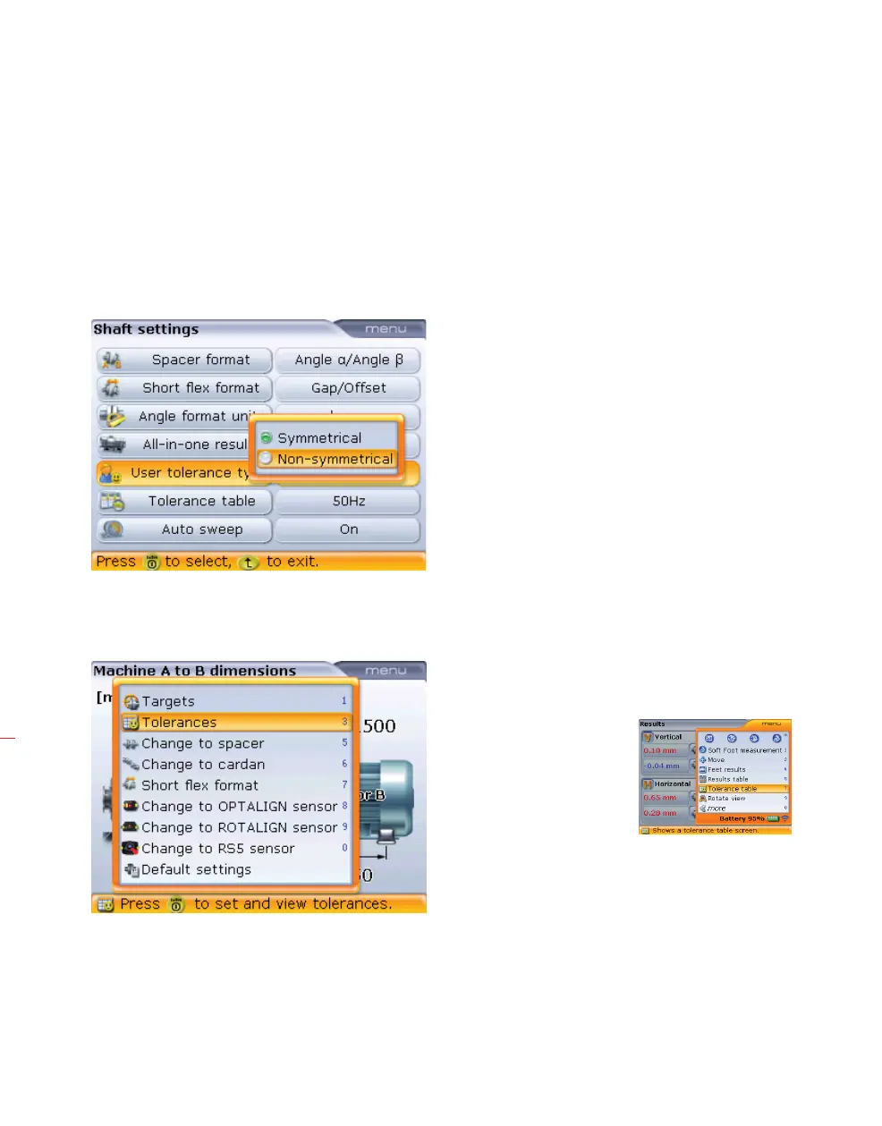
The “Shaft settings” screen
is accessed via the menu
item ‘Configuration’. To
set ‘Symmetrical’ or Non-
symmetrical’ user defined
tolerances, highlight the
item ‘User tolerance type’
and then press
e. Use
f/g to highlight
desired type and then
confirm selection by
pressing
e.
The coupling parameters
context menu is displayed
by pressing
e with the
coupling highlighted.
Note that the “User
defined tolerances /
Tolerance table “ screen
may also be accessed
via the “Results” screen
context menu item
‘Tolerance table’.