Page 28
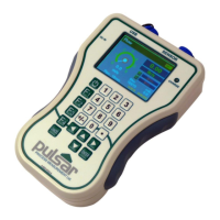
5) Set the “Wake Time”. This is the time duration in which both the
controller and the sensor will be fully powered to perform logging
according to the set logging interval. This is set in units of second.
Example 1: Wake up for 30 seconds every 1 minute to perform logging. Set
Sleep Time to 30 seconds and Wake Time to 30 seconds.
Example 2: Wake up for 30 seconds every 5 minutes to perform logging.
Set Sleep Time to 270 seconds (5 min x 60 seconds less 30 seconds wake
time), and Wake Time to 30 seconds.
If the Sleep Time is less than 10 seconds, or the Wake Time is less than 20
seconds, the Flow Pulse sensor will not be powered-down during sleep,
resulting in higher power consumption. Instead, the Flow Pulse will be
put into low-power mode (only supported on Flow Pulse firmware 1.2.4
or later, otherwise the Flow Pulse sensor remains on full-power).
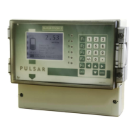
If the “Sleep Time” is more than 10 seconds and the “Wake Time” is more
than 20 seconds, the Flow Pulse Handheld will be powered down
during sleep mode. However, if these two requirements are not met, neither
unit will be powered off during sleep mode.
6) To activate “Slp/Wke Mode” set the “Slp/Wke Mode” to 1.
7) Diagnostic traces will be activated and saved. If this is not required,
press the F1 key to disable traces.
Important Information
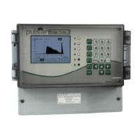
Due to the possibility of power-off while using sleep/wake logging, the mA
output on the Flow Pulse may be interrupted. This may be an issue in
cases where the Flow Pulse is permanently installed and its mA output
is separately monitored for flow. Use the normal data logging function
instead. Alternatively, only connect the RS 485 between the controller and
Flow Pulse, allowing the installed Flow Pulse to be powered
independently. This will avoid mA output interruption when the handheld
controller goes into Sleep. Unplug from controller before cabling work, and
isolate power supply wires from controller to prevent short or contact with
any other terminals on the Flow Pulse.