73
Caution:
The last port of Ethernet Switch is for the MBMS.
Attention:
Les deux côtés du câble de communication de BMS à MBMS doivent être
marqués avec des étiquettes.
Caution:
From the 1st port to the nth port are for the corresponding battery string
(PowerCube-M1-C). So we can fastest find out the corresponding battery string on the
Ethernet Switch.
Attention: Du 1er port au nème port correspondent à la chaîne de batterie correspondante
(PowerCube-M1). Ainsi, nous pouvons trouver rapidement la chaîne de batterie
correspondante sur le commutateur Ethernet.
III. ADD Switch Setting (Address Assignment)
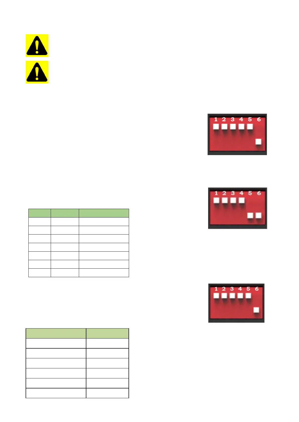
ADD Switch - Battery Controller is a 6-bit dial switches to manually distribute the
communication address of the battery system. Down position is OFF, means
“0”. Up position is ON, means “1”. 1st bit to 5th bit is for address, and the 6th bit
dial switch support a 120Ω resistance (Terminal Resistance).
ADD Switch - MBMS is a 6-bit dial switches to manually distribute the
communication address of the battery system. Down position is OFF, means
“0”. Up position is ON, means “1”. 1st bit to 4th bit is for address, the 5th and the
6th bit dial switch support a 120Ω resistance (Terminal Resistance).
A. Under communication for single BMS (battery string qty. 1 set)
The BMS’s first five bits must set in below <BMS’s Address Configure Table >. The last BMS’s terminal resistance
must set in “1” (X=1);
The address is configured following ASCII code: (“X” is terminal resistance).
BMS’s Address Configure Table:
CAN
Modbus
Address dial bit
0
1
00000X
1
1
10000X
2
2
01000X
3
3
11000X
4
4
00100X
5
5
10100X
6
6
01100X
B. Under CAN Communication Mode between MBMS and BMS (battery string
qty. s6 set) The BMS’s first five bits must set in below <BMS’s Address
Configure Table >. The last BMS’s terminal resistance must set in “1” (X=1),
and other BMS’s terminal resistance must set in “0”.
The address is configured following ASCII code: (“X” is terminal resistance).
BMS’s Address Configure Table:
B
a
tt
e
ry
S
tr
i
ng
A
dd
r
e
ss
B
i
t
1
10000
X
2
01000
X
5
10100
X
6
01100
X