Page 102 of 110 150821/A4 Interface
3.3 Bias Voltage
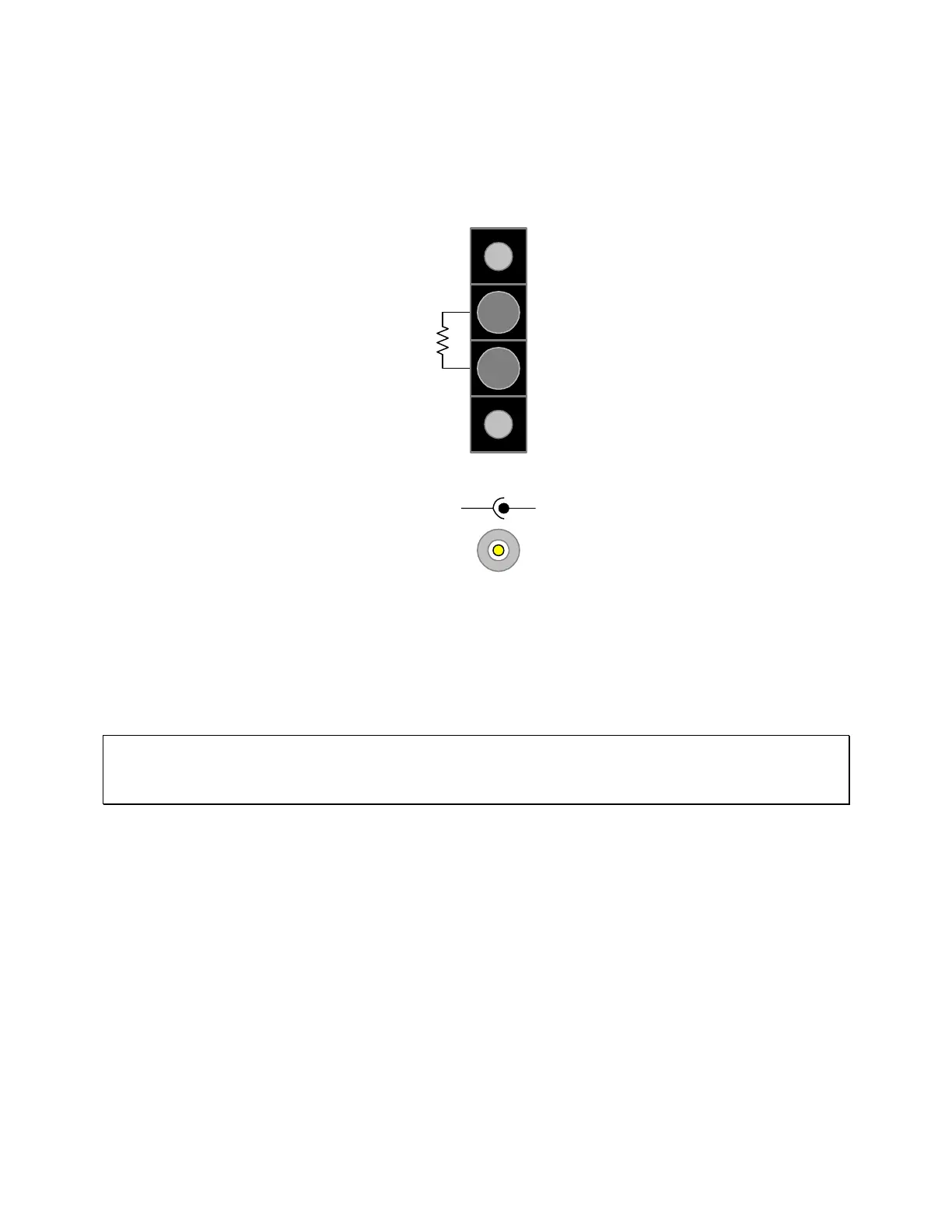
Figure 3-10 illustrates the two connectors on the rear panel of the 1730T instrument used for bias
voltage (or current) applications. The R
BIAS
connector is a black 4-screw terminal strip with two
screws active. The EXT BIAS connector is a silver BNC terminal.
Figure 3-10: Bias Voltage Connectors
A fixed resistor or potentiometer can be connected to R
BIAS
to provide an internal bias voltage or
current to the device under test (DUT). In [MEAS DISPLAY] select Bias Voltage = ON. The
value of the resistor placed across the R
BIAS
terminals determines the bias voltage output. The
R
BIAS
output range is from 0V – 5V. The polarity is always positive. Refer to Table 3-12.
NOTE:
To prevent damage to the 1730T instrument, do not use the R
BIAS
resistor if the EXT BIAS
connector is used.
R
BIAS
can also be used as a bias current source. The output current is determined by the resistor
value and the selected source impedance value with a maximum bias current equal to 200mA
and a compliance voltage of 5.0V. The calculation of the Bias Current is affected by the
Constant Source (impedance) mode as listed in Table 3-11.
Use the EXT BIAS BNC connector if an external power supply is to be used rather than R
BIAS
.
EXT BIAS
(-) (+)
R
BIAS