Page 18 of 110 150821/A4 Introduction
1.3 Controls and Indicators
1.3.1 Front Panel Controls and Indicators
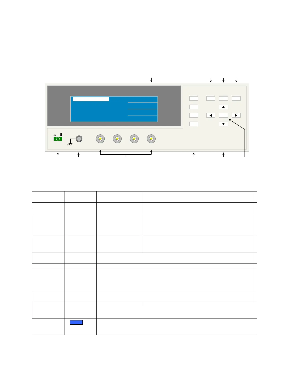
Figure 1-2 illustrates the controls and indicators on the front panel of the 1730T LCR Meter
instrument. Table 1-1 identifies them with description and function.
Figure 1-2: 1730T Front Panel Controls & Indicators
Table 1-1: 1730T Front Panel Controls & Indicators
Reference #
Figure 1-2
Name Type Function
1 Green Push Button Apply AC POWER: 1=ON, 0=OFF
2 Silver Banana Jack Chassis ground connection
3 L
CUR
L
POT
H
POT
H
CUR
4 silver BNC
terminals
Current Drive Terminal, Low (-)
Voltage Sense Terminal, Low (-)
Voltage Sense Terminal, High (+)
Current Drive Terminal, High (+)
4 F1, F2, F3
and F4
4 gray push buttons Select Instrument Functions
Keys perform different functions under different menus.
Right side of display shows corresponding key function.
5 ◄, ▼, ►, ▲ 4 gray push buttons Move backlit box around display to choose parameter
Change parameter value (increase/decrease)
6 TRIGGER Gray push button Initiate measurement
7 SYSTEM
SETUP
Gray push button View, Select or Change System Parameters:
GPIB, Trigger, Handler, Constant source, VM/IM
display, Average, Beeper, Sound, Alarm, Contrast,
Integer, Cable Length, Key Lock & Link 1320
8 MAIN
INDEX
Gray push button View, Select or Change Setup & Result Parameters:
Binning, Compare, Correction & Store & Recall
9 MEAS
DISPLAY
Gray push button View, Select or Change Measurement Parameters:
Frequency, Voltage, Parameter (Pri/Sec), Range, Speed,
Trigger, Bias Voltage, Binning and Compare
10 240 x 64 LCD
display
Show measurement results as value, deviation,
%deviation, bin number or pass/fail.
Show programming instructions
1730T LCR Meter
L
CUR
H
CUR
H
POT
L
POT
QuadTech
(-) (+)
F1
F4
F3
F2
F1
F3
F2
MEAS
DISPLAY
F4
TRIGGER
MAIN
INDEX
SYSTEM
SETUP
01
l
<MEAS DISPLAY>
NEXT PAGE 1/4
PARA : Cs - D
LEVEL : 1.00 V
FREQ. : 100 kHz
Cs : 1.2345 pF
D : 1.2345
1 423 56
98710