EasyManua.ls Logo

QuadTech 1855 - User Manual

QuadTech 1855
76 pages
Print Icon
To Next Page IconTo Next Page
Loading...
1855
Capacitor Leakage Current/IR Meter
Instruction Manual
Form 150767/A4
©QuadTech, Inc., 2004
5 Clock Tower Place, 210 East
Maynard, Massachusetts, U.S.A. 01754
October 2006
Telephone 978-461-2100
Sales 800-253-1230
Facsimile 978-461-4295
Website www.quadtech.com
The material in this manual is for informational purposes only and is subject to change, without notice.
QuadTech assumes no responsibility for any error or for consequential damages that may result from the
misinterpretation of any procedures in this publication.
CAUTION
Voltage may be present on front and rear panel terminals. Follow all warnings in this manual when
operating or servicing this instrument. Substantial levels of energy may be stored in capacitive devices
tested by this unit.
!
Product will be marked with this symbol (ISO#3864) when it is necessary for the user to refer to
the instruction manual in order to prevent injury or equipment damage.
Product marked with this symbol (IEC417) indicates presence of direct current.
Product will be marked with this symbol (ISO#3864) when voltages in excess of 1000V are
present.
Question and Answer IconNeed help?

Do you have a question about the QuadTech 1855 and is the answer not in the manual?

Overview

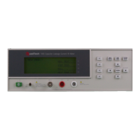
The QuadTech 1855 is a Capacitor Leakage Current/IR Meter designed for testing various passive components, including aluminum foil electrolytic capacitors and high dielectric ceramic capacitors. It also proves useful for testing components where leakage current is a significant factor, such as Zener diodes and absorbers. For production environments, the 1855 includes a Compare function with Pass/Fail indication.

Function Description:

The 1855 instrument measures four key parameters: Leakage Current (LC), Insulation Resistance (IR), Rise Time (Tr), and Withstand Voltage (Vf). It can display two parameters simultaneously. The device offers both automatic sequence tests and manual step tests. A Null function allows for correction of lead leakage, ensuring maximum measurement accuracy. The Compare function enables users to set upper and/or lower limits for LC and IR tests, providing Pass/Fail indications based on measured results. The instrument can be operated continuously or triggered externally or manually.

Important Technical Specifications:

  • Leakage Current Test:

    • Leakage Current Range: 0.001µA – 20.0mA
    • Accuracy: ±(0.3% + 0.005µA)
    • Test Voltage: 1.0V – 650V DC, 0.1V/Step
    • Voltage Accuracy: ±(0.5% + 0.2V)
    • Test Current: 0.5mA – 500mA (for DCV ≤ 100V), 0.5mA – 150mA (for DCV > 100V), 0.5mA/Step
    • Charge Current Accuracy: ±(3% + 0.05mA)
  • Insulation Resistance Test:

    • Insulation Resistance Range: 10Ω – 99.99GΩ
    • IR Accuracy: ±[0.6 + (20V/Vm) + (0.5µA/Im)] x [1 + (0.005µA/Im)]% (where Vm and Im are measured voltage & current)
    • Test Voltage: 1.0V – 650V DC, 0.1V/Step
    • Voltage Accuracy: ±(0.5% + 0.2V)
    • Test Current: 0.5mA – 500mA (for DCV ≤ 100V), 0.5mA – 150mA (for DCV > 100V), 0.5mA/Step
    • Charge Current Accuracy: ±(3% + 0.05mA)
  • Withstand Voltage Test:

    • Rise Time (Tr): 0.05s – 120s
    • Withstand Voltage (Vf): 1.0V – 650V DC, 0.1V/Step
    • Test Current: 0.5mA – 150mA, 0.5mA/Step
    • Charge Current Accuracy: ±(3% + 0.05mA)
    • Measure Time: 30s – 600s
    • MAX Charge Time: 5s – 600s
  • General Features:

    • Monitored Voltage (Vm): 1.0V – 650V DC (Voltage across DUT)
    • Charge Time: 0 – 999 seconds (1s/10s increments <100s; 100s increments >100s)
    • Delay Time: 0.2 – 999 seconds (0.1s increments <100s; 10s increments >100s)
    • Discharge: 65 Watt Discharge Circuit
    • Trigger Delay: 0 – 9.995 seconds in 0.1s increments
    • Trigger Edge: Falling or Rising
    • Measurement Mode: Continuous or Trigger (INT, EXT or Manual)
    • Measurement Rate: Fast (18 measurements/second), Medium (14 measurements/second), Slow (7 measurements/second)
    • Ranging: Automatic or Hold
    • Averaging: 1-8 measurements
    • Display: 240 x 64 LCD Graphic display
    • Indication: Audible alarm programmable HI, LOW or OFF for Pass or Fail
    • Standard Interface: RS232
    • Optional Interfaces: IEEE-488 & Handler
    • Connectors: 1 BNC terminal (Input), 2 Banana terminals (HV (+), HV (-)), 1 Banana Socket (Chassis Ground)
    • Front Panel Lockout: Keypad Lock
  • Mechanical:

    • Bench Mount
    • Dimensions (w x h x d): 12.50 x 4.00 x 13.50 inches (317.2 x 101.5 x 342.6 mm)
    • Weight: 18 lbs (8.2kg) net, 22 lbs (10kg) shipping
  • Environmental:

    • Operating Temperature: 10°C to 40°C
    • Storage Temperature: -10°C to 50°C
    • Humidity: <90%
    • Pollution Degree: 2
    • Installation Category: I
  • Power:

    • 90-125VAC or 190-250VAC
    • 50 or 60Hz
    • 400W max

Usage Features:

  • Easy Setup: The instrument features a user-friendly interface with main menus (MEAS DISPLAY, MAIN INDEX, SYSTEM SETUP) accessed via function keys (F1-F4) and arrow keys for parameter selection and value adjustment.
  • Null Function: Essential for accuracy, the Null function allows users to zero out the effects of stray leakage from test leads or fixtures. It is recommended after power-up, parameter changes, or lead/fixture changes.
  • Compare Function: Facilitates production testing by setting upper and lower limits for LC and IR tests, providing immediate Pass/Fail feedback.
  • Flexible Triggering: Supports internal, external, and manual triggering modes, with programmable trigger delay and edge selection (falling or rising).
  • Measurement Speed Control: Users can select between Fast, Medium, or Slow measurement rates to balance speed and accuracy requirements.
  • Averaging: Improves measurement stability by averaging 1 to 8 measurements.
  • Voltage Monitoring: The EXT Vm Display feature allows monitoring of the voltage across the Device Under Test (DUT) during measurements.
  • Audible Alarms: Programmable beeper loudness and alarm modes (pulse or continuous) for Pass or Fail results.
  • Key Lock: Provides a front panel lockout feature, preventing accidental changes to programmed settings during operation.

Maintenance Features:

  • Self-Test: The instrument includes a self-test function to verify its internal components (RAM, EEPROM, CPLD) and calibration data.
  • Calibration: The 1855 is factory-calibrated with a NIST calibration certificate. Annual verification is recommended using the 1855-TP Test Procedure. Calibration adjustments should only be performed by qualified service personnel to maintain warranty.
  • Fuse Replacement: Instructions are provided for safely changing the power line fuse on the rear panel, ensuring proper rating for the selected line voltage.
  • Service Policy: QuadTech maintains product repair capability for at least five years after original shipment.
  • Technical Support: Applications engineers are available for technical assistance, and a Customer Care Center (CCC) handles Return Material Authorization (RMA) for service.

Safety Precautions:

The 1855 can output up to 650V DC, and capacitive devices can store significant charge. Users must operate the instrument with its chassis connected to earth ground, ensure proper BNC cable connection to the INPUT terminal, and never touch test leads or DUT when output is applied. All capacitive devices must be fully discharged before handling. In emergencies, the power switch should be turned OFF, and the AC power cord disconnected. The maximum input current of 1A should not be exceeded.

QuadTech 1855 Specifications

General IconGeneral
BrandQuadTech
Model1855
CategoryMeasuring Instruments
LanguageEnglish

Related product manuals