Page 15 of 76
Condensed Operating Instructions
General Information
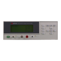
The 1855 Capacitor Leakage Current/IR Meter is an instrument for measuring the parameters of
leakage current (LC), insulation resistance (IR), withstand voltage (WV) and rise time (Tr). The
1855 instrument functions mainly as a leakage current and withstand voltage tester for aluminum
foil electrolytic capacitors and high dielectric ceramic capacitors. The 1855 instrument is useful
in testing any components for which leakage current is a major factor including Zener diodes,
absorbers, etc. For production testing, the 1855 instrument has a Compare function and Pass/Fail
indication. Connection to device under test is through BNC/Banana terminals on the front panel.
Start-Up
The 1855 Capacitor Leakage Current/IR Meter can be operated from a power source between 90-
125V or 190-250V AC at a power line frequency of 50 or 60Hz. The standard 1855 unit is
shipped from QuadTech with a 4A fuse in place for AC 90-125V operation. (A 2A fuse is
included for AC 190-250V operation). The 1855 unit is shipped with the line voltage selector set
for 115V. Refer to paragraph 1.4.3 for instructions on changing the fuse or line voltage selector.
Connect the 1855 Capacitor Leakage Current/IR Meter’s AC power cord to the source of proper
voltage. Operate the 1855 instrument with its chassis connected to earth ground. The 1855
instrument is shipped with a three-prong power cord to provide this connection to ground. This
power cord should only be plugged into a receptacle that provides earth ground. Serious injury
may result if the 1855 instrument is not connected to earth ground.
To turn the 1855 instrument ON, press the power button on the front panel. To switch the power
OFF, press the button again or if measurements are to be made proceed with the Test Parameter
Setup in Table COI-1. The 1855 instrument should warm up for 15 minutes prior to use.
Table COI-1: Test Parameter Setup
Test LC/IR WV/Tr
Parameter
Test V 1.0V – 650V DC N/A
C.C. 0.5mA – 500mA N/A
Range 2uA-20uA-200uA-2mA-20mA N/A
CHG T 0s – 999s N/A
DWELL T 0.2s – 999s N/A
Speed Fast – Medium – Slow N/A
Vf N/A 1.0 – 650V DC
C.C. N/A 0.5mA – 150mA
Tend N/A 30s – 600s
CHG Tend N/A 5s – 600s
NOTE
Refer to paragraphs 2.3.3 through 2.4 for a full description of programming test parameters. Test parameters must
be set before the 1855 instrument can be zeroed.