Page 38 of 76 Interface
2.4.4 Withstand Voltage Test
To access the Withstand Voltage Test, press [MAIN INDEX] and [F4] = NEXT PAGE 1/2 and
then press [F1] = W.V. TEST. The MEAS DISPLAY menu will appear. Program the Test
Voltage, Constant Current, Measurement Time and maximum Charge Time. Refer to paragraphs
2.5.8 through 2.5.10 for programming details.
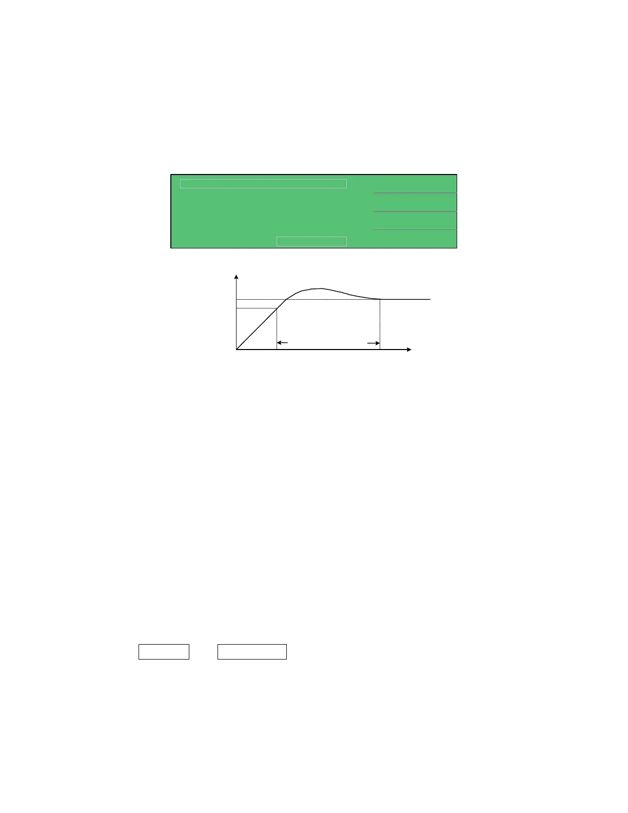
50.0V
2.0mA
CHG Tend
30S
Tr :
< MEAS DISPLAY: W.V. TEST >
S
Vf
C.C.
Tend
:
:
:
DISCHARGECHARGE TEST
Vm = 0.0V
Vt : V
5S:
TendTr0
Vf
Vt
(t)
(V)
0
Withstand Voltage Time
58.0V/30.15S
0.15
58.00
Figure 2-7: Withstand Voltage Parameters
Withstand Voltage is the voltage at which the product’s insulation begins to break down. There
are however many definitions for Withstand Voltage. The 1855 instrument and this manual use
the WV terminology from the EIAJ RC-2364A standard, “Test Methods of Electrode Foils for
Aluminum Electrolytic Capacitors”.
Vf: The standard dielectric withstand voltage
CC: The constant charge current for the WV test
Tend: The measurement time for the WV test. Tend = Tr+ the programmed test time.
CHG. Tend: The maximum charge time for the WV test.
Tr: The time between the start of the current application and the voltage reaching
90% of rated withstand voltage (Vf).
Vt: The measured voltage at the end of the WV test.
Figure 2-7 illustrates a Withstand Voltage test. The following parameters were set: Vf=50V,
CC=2mA, Tend=30seconds and CHG Tend=5seconds. After [TRIGGER] is pressed, the results
shown in Figure 2-7 are Rise Time (Tr) = 0.15seconds and Measured Voltage (Vt) = 58.00V. In
the bottom left-hand corner above the test status boxes (CHARGE – TEST – DISCHARGE) are
two results: Vm=0.0V and 58.0V/30.15S. The Vm=0.0V box is the monitor of the output
voltage during the test. The 58.0V/30.15S box is the last measured voltage and time when the
test ended.