Introduction Page 21 of 76
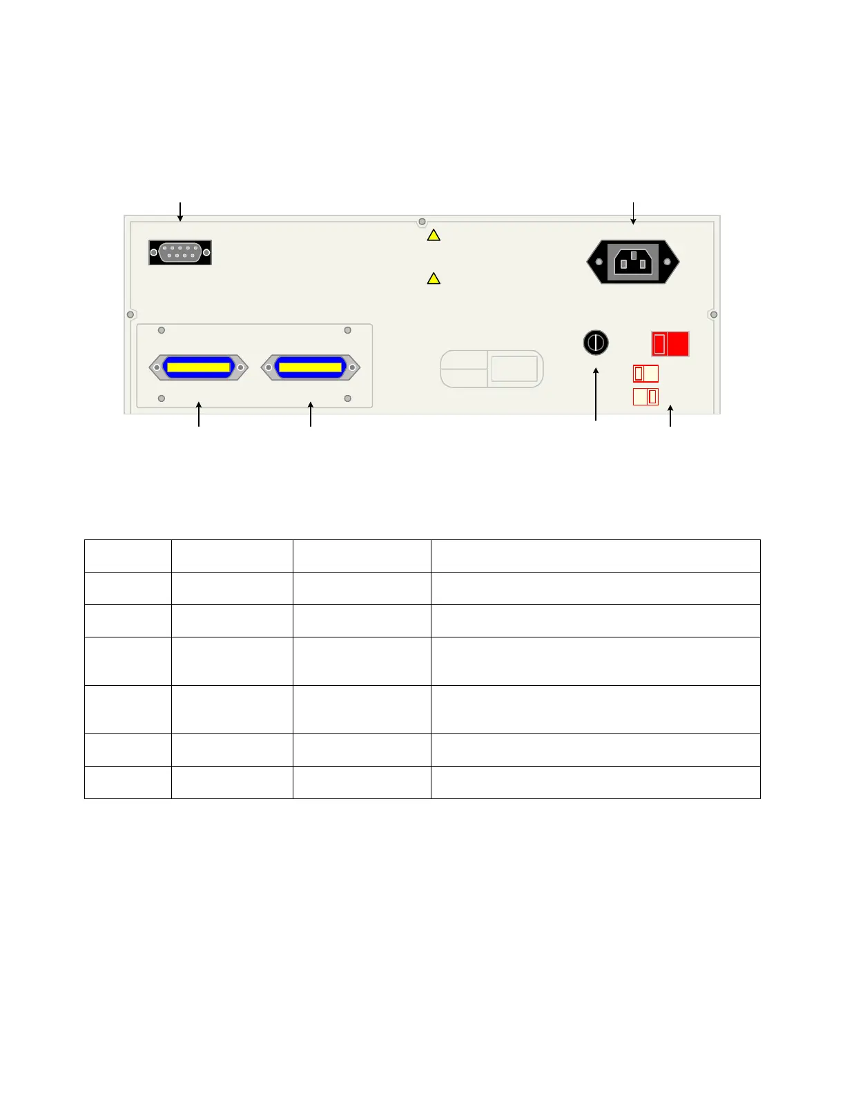
1.3.2 Rear Panel Controls and Connectors
Figure 1-3 illustrates the controls and connectors on the rear panel of the 1855 Capacitor Leakage
Current/IR Meter instrument. Table 1-2 identifies them with description and function.
1
56
234
RS232
!
!
POLLUTION DEGREE 2
INSTALLATION CATEGORY I
MODEL NO.
SERIAL NO.
IEEE-488 INTERFACEHANDLER INTERFACE
FUSE LINE VOLTAGE
SELECTED
115V
230V
115V
WARNING:
FOR CONTINUED PROTECTION
AGAINST FIRE HAZARD, REPLACE ONLY
WITH THE SAME TYPE AND RATING OF FUSE
AS SPECIFIED FOR THE LINE VOLTAGE
BEING UTILIZED.
CAUTION:
NO OPERATOR SERVICEABLE
PARTS INSIDE. REFER SERVICING TO
QUALIFIED PERSONNEL.
90V - 125V~
T4.0AL 250V
190V - 250V~
T2.0AL 250V
115V ~/230V~
50/60Hz 400VA MAX
Figure 1-3: Rear Panel 1855 Instrument
Table 1-2: 1855 Rear Panel Controls & Connectors
Reference #
Figure 1-3
Name Type Function
1 HANDLER
INTERFACE
Blue 24-pin
connector
Handler Interface connector for remote operation
2 IEEE-488
INTERFACE
Blue 24-pin
connector
IEEE-488 Interface connector for data transfer
3 FUSE Black screw cap fuse
holder
Short circuit protection
T 4A 250V fuse for 115V operation
T 2A 250V fuse for 230V operation
4 LINE VOLTAGE
SELECTED
2 Red 2-position
Slide Switches
Select Voltage Level corresponding to AC Source
90V – 125V: T4.0A 250V fuse
190V – 250V: T 2A 250V fuse
5 AC Line Input Black 3-wire inlet
module
Connection to AC power source
6 RS-232
INTERFACE
Black 9-pin RS-232 interface for serial communication