Interface Page 73 of 76
3.3.1 Trigger
Paragraph 2.3.16 contains the instructions for changing the Handler mode. Paragraphs 2.3.3 and
2.3.4 contain instructions for setting the Trigger Delay time and selecting the Trigger Edge.
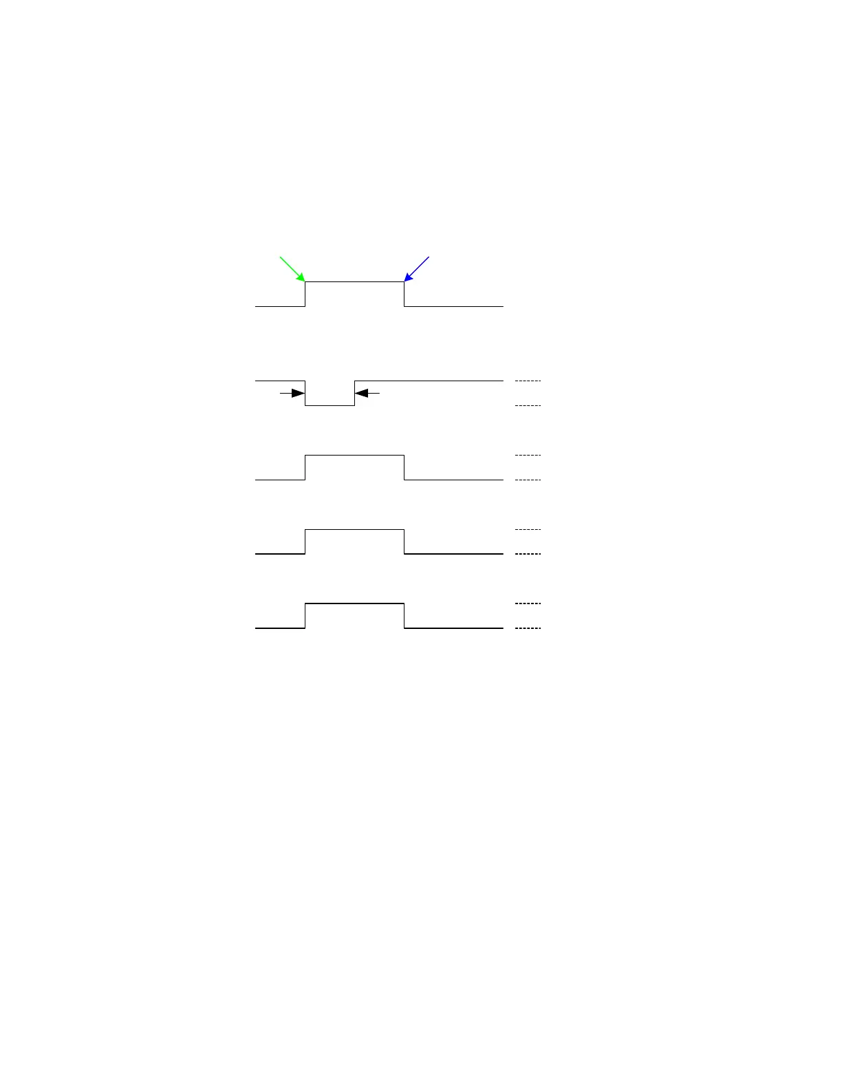
Figure 3-5 illustrates the Trigger function.
Figure 3-5: Trigger
Output Signals
The output lines of the 1855 Handler interface are open collector drivers that pull each signal line
to a low voltage, signal ground when the signal is active (true). Each external line should be
pulled up (with a resistor) to a positive voltage between 5V and 24V. The pull-up resistor must
limit the current to < 6mA for a signal of a comparison function and to < 5mA for a control
signal (EOT).
Input Signal
The input signal to the 1855 Handler interface is active low and requires a positive external
voltage to pull the signal down below 0.4V, ground.
ACQ OVER
EOT
BIN
START
c
e
d
f
+2.5V < Vh < 5V
0V < Vl < 0.4V
Vh < 24V
Ih < 6mA (for Vl < +0.4V)
Vh < 24V
Ih < 6mA (for Vl < +0.4V)
Ih < 6mA (for Vl < +0.4V)
Vh < 24V
1uS
minimum
RISING FALLING
Start measurement on RISING or FALLING edge
Trigger
DELAY