Interface Page 51 of 76
Section 3: Interface
3.1 RS-232 Interface
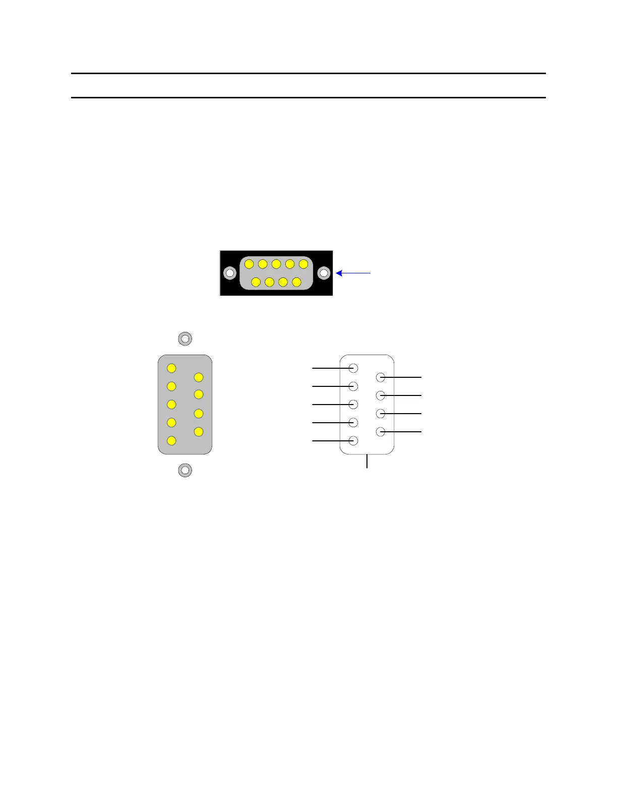
3.1.1 RS-232 Pin Configuration
The 1855 instrument comes standard with an RS232 Interface for remote operation. Connection
is through the black/silver 9-pin connector labeled ‘RS232’ on the rear panel of the 1855
instrument. Figure 3-1 illustrates the designation of the pins on the RS232 connector. The
connection cable must be a ‘straight through’ cable for the 1855 unit to communicate.
6
7
8
9
1
2
5
3
4
RS232
1
Figure 1-3
1
9
8
7
6
5
4
3
2
Clear to Send
Shield
Transmitted Data
Received Data
Data Set Ready
Signal Ground
Request to Send
DB9 Female
Data Terminal Ready
Ring Indicator
Data Carrier Detected
Figure 3-1: RS-232 Interface Pin Configuration
3.1.2 RS232 Specifications
Data Bits: 8
Stop Bits: 1
Parity: None
Baud Rate: 600, 1200, 4800, 9600, 19200 or 28800bps, Software selectable
EOS: CR + LF
Echo: Off