Interface Page 27 of 76
2.2 Startup
Check to make sure the red Line Voltage Selector switch on the rear panel agrees with the power
source available. Depending on the power source the switch position should be in the up or down
position as shown in Figure 1-5 (Close-Up of 1855 Rear Panel).
CAUTION
USE ALL PRECAUTIONS NECESSARY TO AVOID TOUCHING THE DEVICE UNDER TEST WHEN THE
TRIGGER BUTTON HAS BEEN PRESSED.
Connect the instrument power cord to the source of proper voltage. The instrument is to be
used only with three-wire grounded outlets.
Power is applied to the 1855 instrument by pressing the green power switch on the front panel to
the ON (1 position). The 1855 unit should warm up for a period of at least 15 minutes prior to
measurements being made.
2.3 SYSTEM SETUP
System Setup contains the 1855 instrument setup functions: Calibration, Memory Manage and
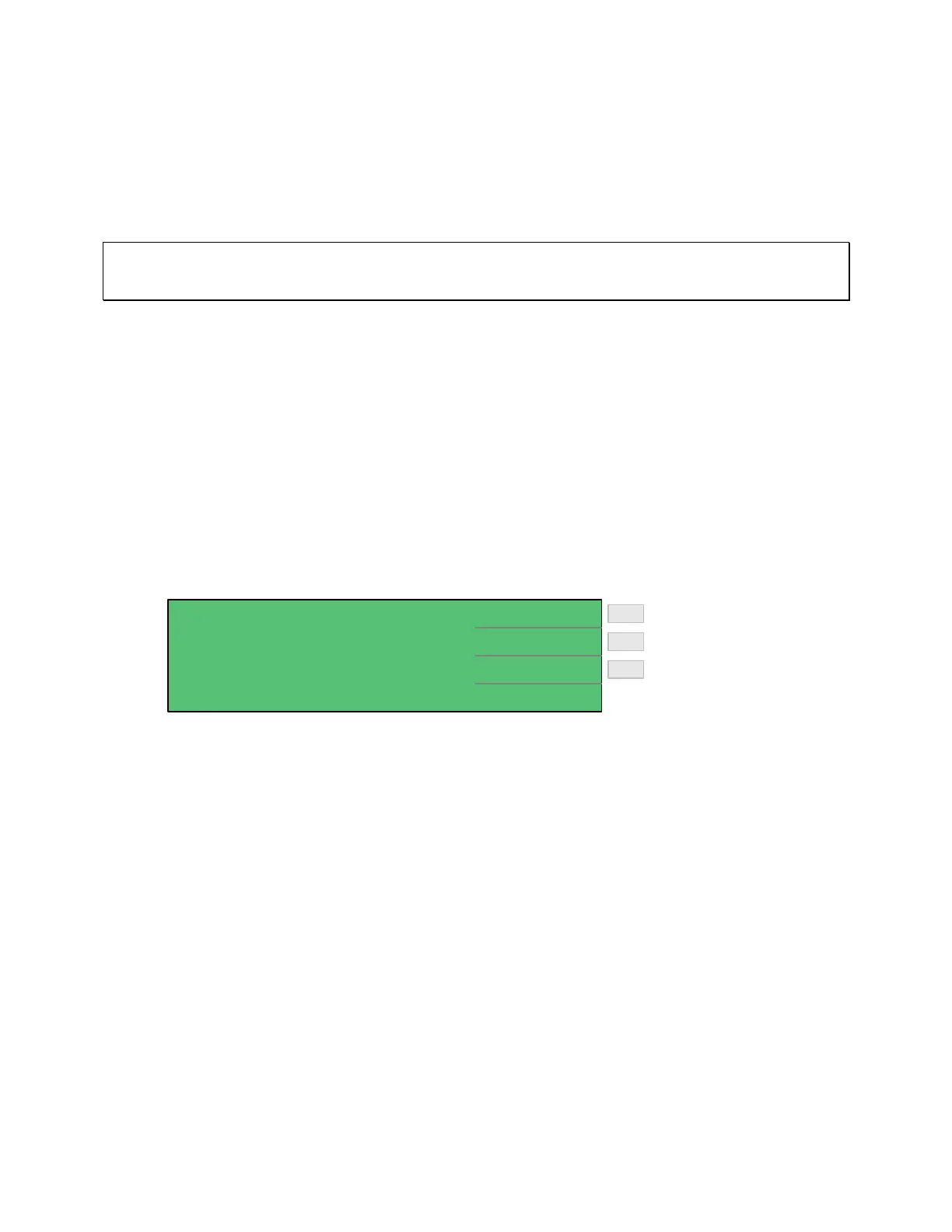
System Configuration. Press [SYSTEM SETUP] to access these functions.
< SYSTEM SETUP > CALIBRATION
MEM MANAGE
SYSTEM CONFIG
Enter Memory Manage
Enter Calibration
Enter System Configuration
F2
F3
F1
Figure: 2-1: System Setup
2.3.1 Calibration
The Calibration menu is to be accessed by Qualified Service Personnel Only. Altering the 1855
instrument calibration will void the instrument warranty. The Calibration function is used to
verify the resistance measurement ranges. To access the calibration function, press [SYSTEM
SETUP] then press [F1] = [CALIBRATION]. Enter the password. [▲] [▼] [►] [◄]
[TRIGGER]. Select cal range 20V or 200V. Refer to paragraph 4.3 Calibration for procedure.
2.3.2 Memory Manage
The Memory Manage menu is to be accessed by Qualified Service Personnel Only. Altering the
1855 instrument memory will void the instrument warranty. The memory manage function is
used to verify the setup of the 1855 unit with a Function Test and a Handler Test. To access the
memory manage function, press [SYSTEM SETUP] then press [F2] = [MEM MANAGE]. Enter
the password. [▲] [▼] [►] [◄] [TRIGGER].