Page 20 of 76 Introduction
1.3 Controls and Indicators
1.3.1 Front Panel Controls and Indicators
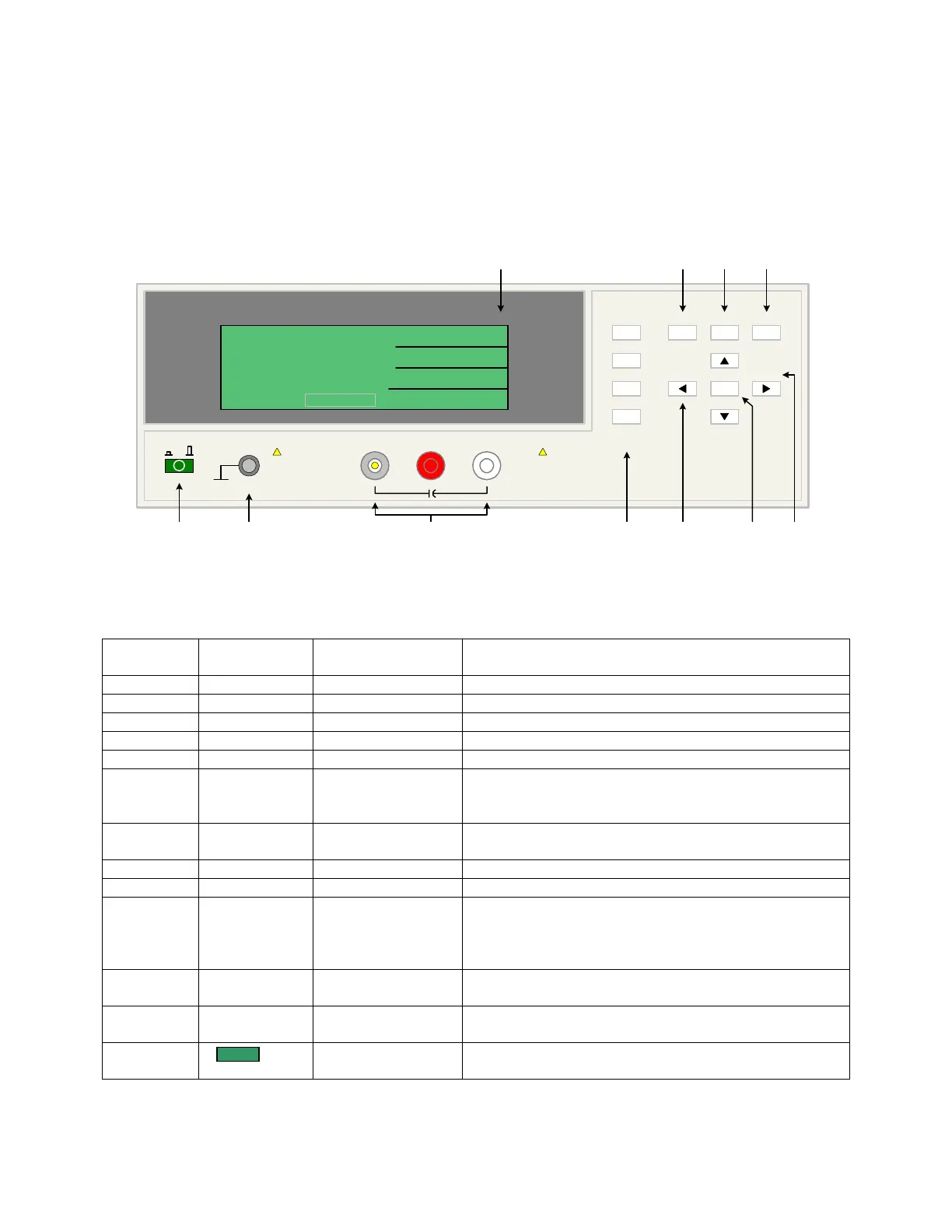
Figure 1-2 illustrates the controls and indicators on the front panel of the 1855 Capacitor
Leakage Current/IR Meter instrument. Table 1-1 identifies them with description and function.
1 423 56
10 9 811
1855 Capacitor Leakage Current /IR Meter
(-)(+)INPUT
QuadTech
+
HV
F1
F4
F3
F2
F1
F3
F2
MEAS
DISPLAY
F4
TRIGGER
MAIN
INDEX
SYSTEM
SETUP
01
l
<MEAS. DISPLAY: SEQ. TEST>
NEXT PAGE 1/2
2
0.5
TEST V
LC :
1.0
C.C
RANGE
1.5 mA
CHARGE/TEST DISCHARGE
CHARGE TEST DISCHARGE
:
:
:
V
mA
uA
-
7
A
Figure 1-2: 1855 Front Panel Controls & Indicators
Table 1-1: 1855 Front Panel Controls & Indicators
Reference #
Figure 1-2
Name Type Function
1 Green Push Button Apply AC POWER: 1=ON, 0=OFF
2 Silver Banana Jack Chassis ground connection
3a INPUT Silver BNC terminal Current Drive Terminal, High (+)
3b HV (+) Red Banana Jack Voltage Sense Terminal, High (+)
3c HV (-) White Banana Jack Voltage Sense Terminal, Low (-)
4 F1, F2, F3 and
F4
4 gray push buttons Select Instrument Functions
Keys perform different functions under different menus.
Right side of display shows corresponding key function.
5 ◄, ▼, ►, ▲ 4 gray push buttons Move backlit box around display to choose parameter
Change parameter value (increase/decrease)
6 TRIGGER Gray push button Initiate measurement
7 DISCHARGE STOP measurement in progress & initiate discharge time
8 SYSTEM
SETUP
Gray push button View, Select or Change System Parameters:
Parameter, Beeper, Sound, Alarm, Trigger, Handler,
Contrast, GPIB, RS-232, Key Lock, Line Frequency,
Charge, Dwell, Average & EXT Vm Display
9 MAIN
INDEX
Gray push button View, Select or Change Setup & Result Parameters:
Sequence, Step, Null, WV Test & Compare
10 MEAS
DISPLAY
Gray push button View, Select or Change Measurement Parameters:
Voltage, Current, Range, Charge, Dwell, Speed & Trigger
11 240 x 64 LCD
display
Show measurement results as value or pass/fail.
Show programming instructions