Page 74 of 76 Interface
3.3.2 Handler Pin Assignments for Compare Operation
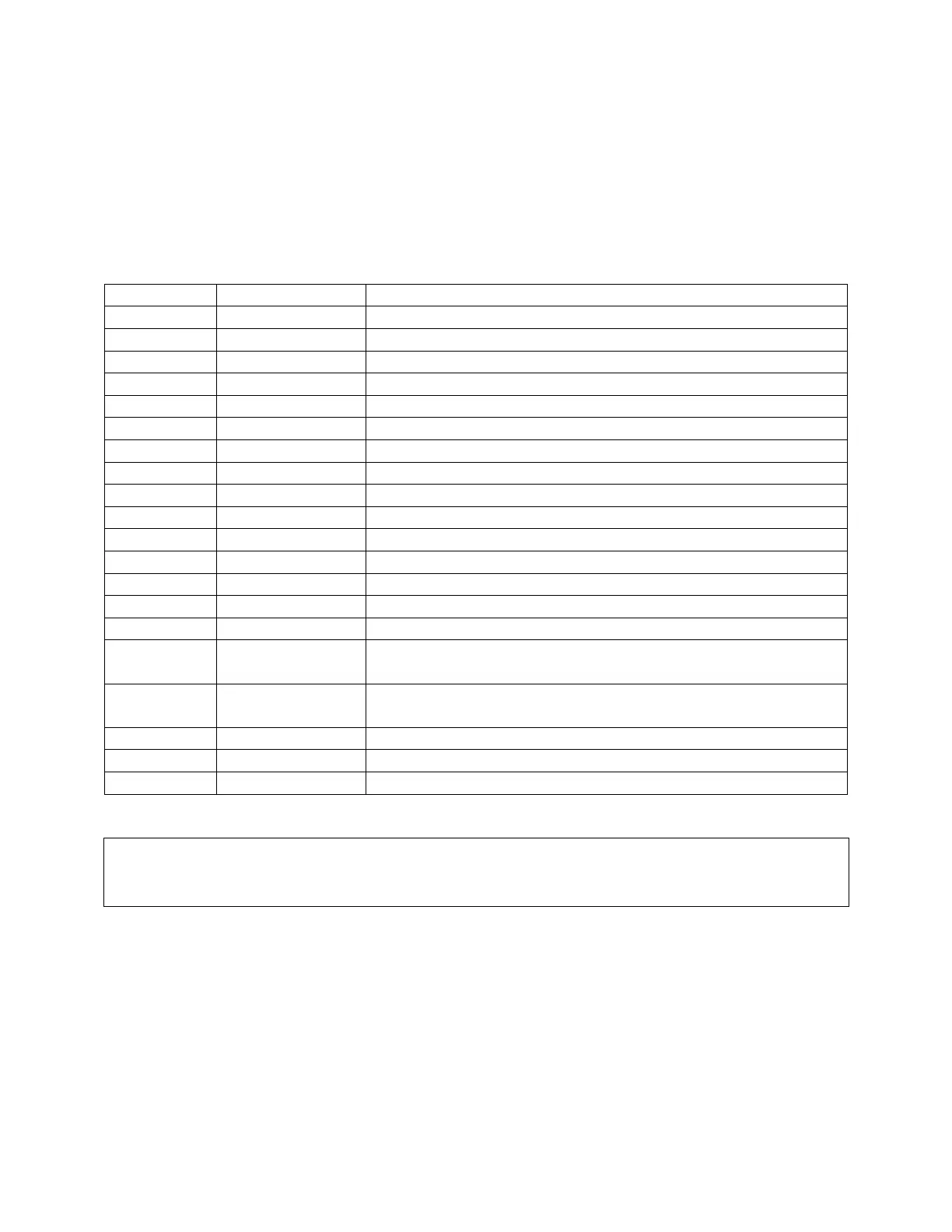
Table 3-7 lists the pin assignments when the handler interface on the 1855 instrument is
performing a Compare operation. The device under test is being compared against a standard of
known value. High and low limits can be defined as absolute value or percent value.
Table 3-7: Handler Pin Assignments for Compare
Pin Name Description
1 /EXT External trigger
2 X No connection
3, 20 /TEST Instrument is in Test mode
4, 24 X No connection
5 - 7 GND Ground external DC
8 COM Common Ground
9, 13 X No connection
10 VEXT External DC voltage: 5V ~ 24V
11 VINT Internal DC voltage: +5V
12 X No connection
14 X No connection
15 /PASS Measured Result is within the upper/lower limit(s) (PASS)
16 /CHARGE Instrument is in Charge mode
17 /FAIL Measured Result is outside the upper/lower limit(s) (FAIL)
18 /EOT End of Test
19 /HI For LC: Measured Result is > Upper Limit
For IR: Measured Result is < Lower Limit
21 /LO For LC: Measured Result is < Lower Limit
For IR: Measured Result is > Upper Limit
22 ACQ Received data, ready to accept next
23 EOT End of Test
45 – 46 /FAIL_CHARGE Instrument is in Discharge mode
NOTE:
When using External DC Voltage (VEXT), Pins 5, 6 & 7 (GND) must be connected to Pin 8
(COM).