Page 26 of 76 Interface
DUT: Device Under Test. (i.e. the product being tested).
Ground: The base reference from which voltages are measured, nominally the same
potential as the earth. Ground is also the side of a circuit that is at the same
potential as the base reference.
Insulation Resistance: Measures the total resistance between any two points separated by electrical
insulation. The IR test determines how effective the dielectric (insulation) is in
resisting the flow of electrical current.
Interface:
Handler: Device for remote control of test instrument in component handling operations.
IEEE-488: General Purpose Interface Bus (GPIB). GPIB is an industry standard definition
of a Parallel bus connection for the purpose of communicating data between
devices.
RS232: An industry standard definition for a Serial line communication link or port.
Range: The resistance ranges the instrument uses for reference in making the
measurement.
Speed: The rate at which the instrument makes a measurement in measurements per
second. Speed is inversely proportional to accuracy.
Trigger: The device for initiating the test (applying the voltage or current).
External: The test is initiated via an external source such as a computer with an IEEE-488
or Handler interface. One measurement is made each time the external trigger is
asserted on the handler.
Internal: The instrument continuously makes measurements.
Manual: The operator initiates the test by pressing the [START] button. One
measurement is made each time the trigger is pressed.
Withstand Voltage: Voltage at which the product’s insulation begins to break down. There are many
definitions for Withstand Voltage. This manual uses the terminology from the
EIAJ RC-2364A standard, “Test Methods of Electrode Foils for Aluminum
Electrolytic Capacitors”.
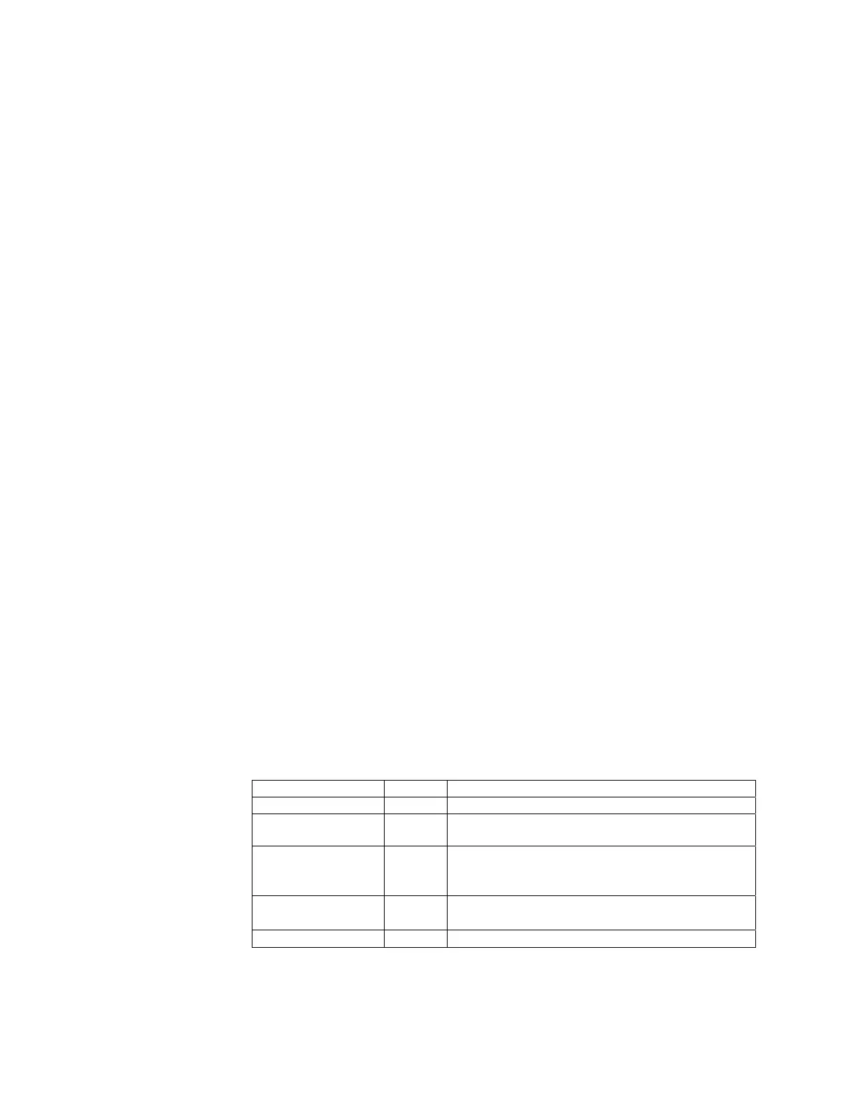
Term Symbol Definition
Formation Voltage Vfe The final applied voltage
Standard Dielectric
Withstand Voltage
Vf The withstand voltage of formed foil
Rise Time Tr The time between when the current is applied and
the voltage reaches 90% of the rated withstand
voltage, Vf.
Withstand Voltage Vt
Tr + 3minutes ±10seconds (formed foils)
Tr + 1minute ±10seconds (unformed foils)
Rated Voltage WV Rated working voltage of a capacitor