Page 100 of 110 150821/A4 Interface
3.2.1 Handler Pin Assignments for Binning Operation
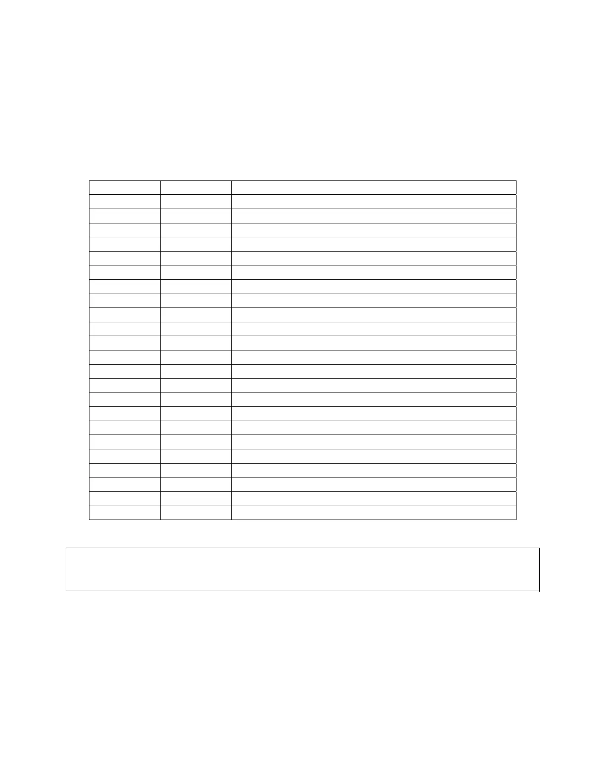
Table 3-9 lists the pin assignments when the handler interface on the 1730T instrument is
performing a Binning operation. The device under test is sorted by test value. The test limits can
be set as absolute value or percent value.
Table 3-9: Handler Pin Assignments for Binning
Pin Name Description
1 – 2 VEXT External DC voltage: 5V ~ 24V
3 – 18 X No connection
19 /EXT External trigger
20 – 21 VEXT External DC voltage: 5V ~ 24V
22 – 25 X No connection
26 – 27 COM Common Ground
28 BIN 8 Primary parameter pass (within Bin 8 limits)
29 BIN 3 Primary parameter pass (within Bin 3 limits)
30 BIN 7 Primary parameter pass (within Bin 7 limits)
31 BIN 5 Primary parameter pass (within Bin 5 limits)
32 BIN 2 Primary parameter pass (within Bin 2 limits)
33 BIN 6 Primary parameter pass (within Bin 6 limits)
34 BIN 0 Secondary parameter fail
35 BIN 1 Primary parameter pass (within Bin 1 limits)
36 BIN 4 Primary parameter pass (within Bin 4 limits)
37 X No connection
38 BIN 9 Primary parameter fail
39 – 42 X No connection
43 ACQ Received data, ready to accept next
44 EOT End of Test
45 – 46 COM Common Ground
47 – 48 X No connection
49 – 50 GND Chassis Ground
NOTE:
When applying VEXT, common ground (COM: pins 45 and 46) must be connected to chassis
ground (GND: pins 49 and 50).