Interface 150821/A4 Page 99 of 110
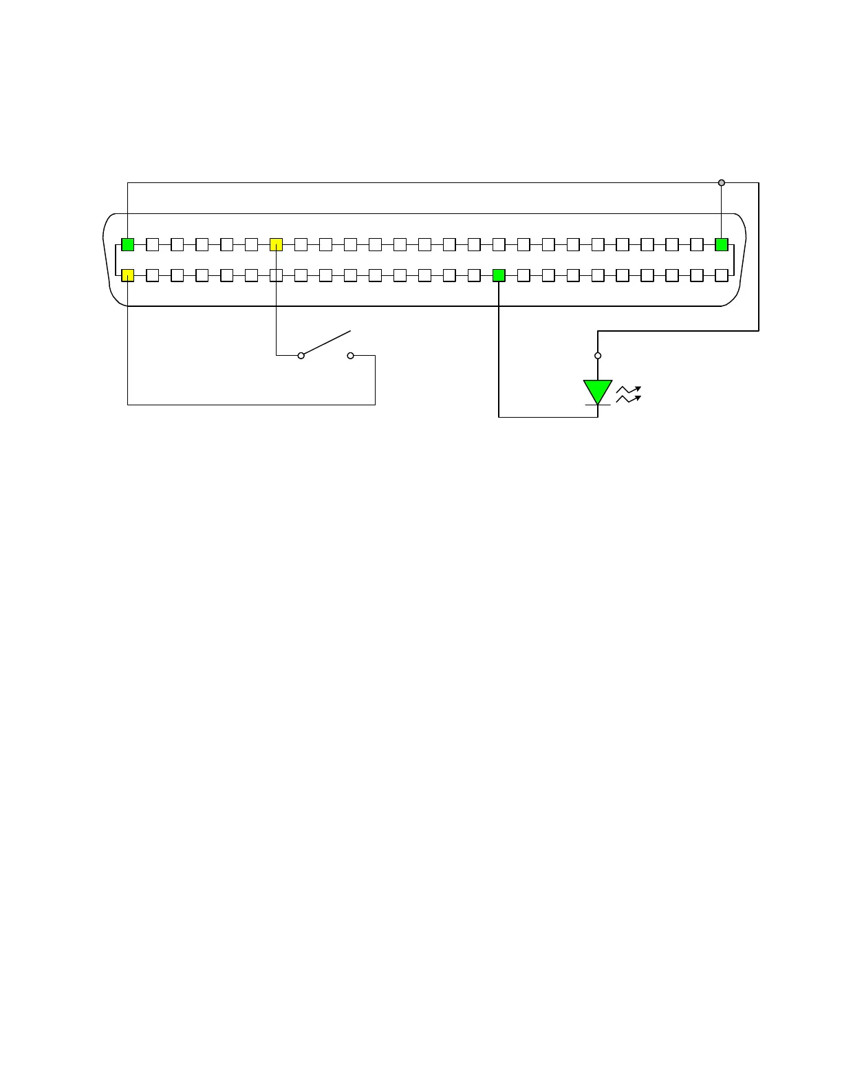
A basic example of an external trigger (START) connection is illustrated in Figure 3-9. A switch
is inserted between pins 19 and 50. A green LED is connected between pins 1, 25 and 35 (Bin 1).
1730T Handler Interface PIN Configuration: Rear Panel View
12 6789101113 1253415 1419 18 17 162024 23 212225
484950 424344454647 363738394041 303132333435 26272829
START
Figure 3-9: Sample External Trigger Connection