Introduction 150821/A4 Page 19 of 110
1.3.2 Rear Panel Controls and Connectors
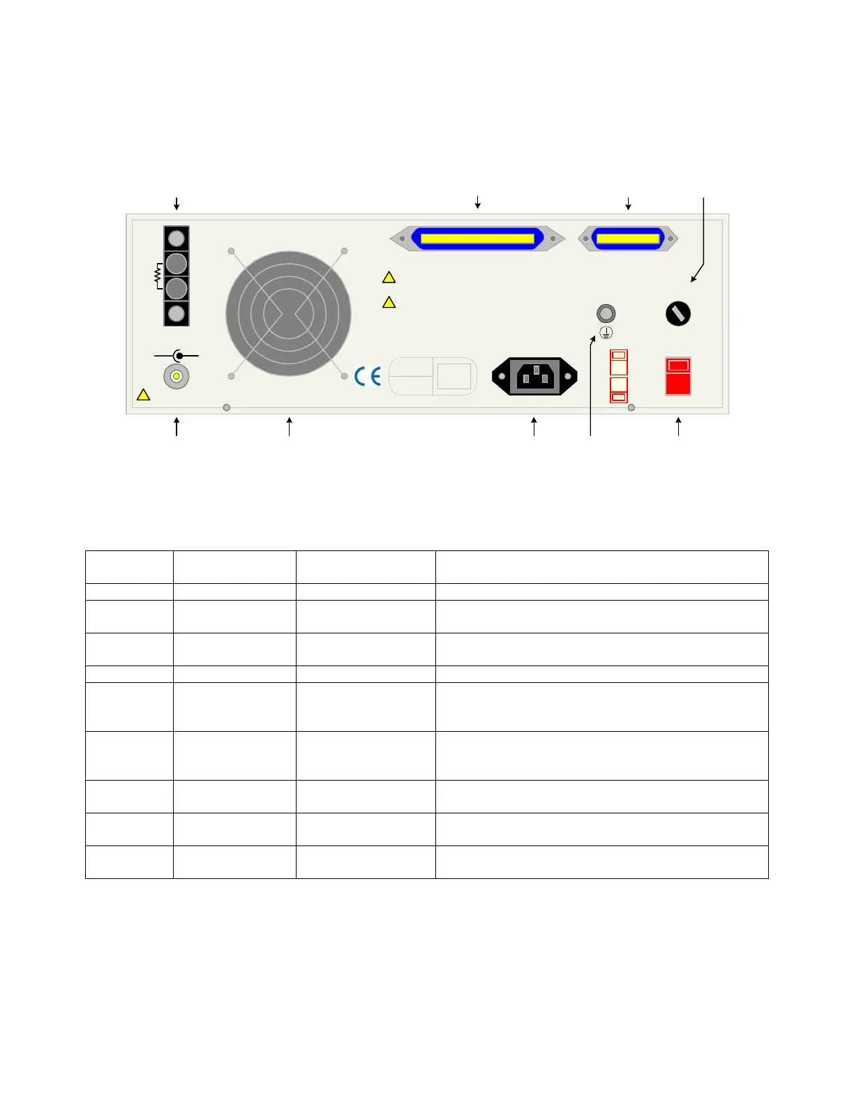
Figure 1-3 illustrates the controls and connectors on the rear panel of the 1730T LCR Meter
instrument. Table 1-2 identifies them with description and function.
1 4235
6879
EXT BIAS
(-) (+)
FUSE
R
BIAS
HANDLER INTERFACE IEEE-488 INTERFACE
GUARD
LINE VOLTAGE
SELECTED
115V
115V
230V
!
!
POLLUTION DEGREE 2
INSTALLATION CATEGORY I
115V ~/230V~
50/60Hz 65W MAX
+5V MAX INPUT
!
MODEL NO.
SERIAL NO.
Figure 1-3: Rear Panel 1730T Instrument
Table 1-2: 1730T Rear Panel Controls & Connectors
Reference #
Figure 1-3
Name Type Function
1 EXT BIAS Silver BNC terminal External Bias Voltage output connection to DUT
2 FAN SF11580AT
115V 50/60Hz 0.10A
Cool Unit: T≥50°C = ON, T<45°C = OFF
3 AC Line Input Black 3-wire inlet
module
Connection to AC power source
4 GUARD Silver banana jack Chassis ground connection
5 LINE VOLTAGE
SELECTED
2 Red 2-position
Slide Switches
Select Voltage Level corresponding to AC Source
90V – 125V: T1.0A 250V fuse
190V – 250V: T 0.5A 250V fuse
6 FUSE Black screw cap fuse
holder
Short circuit protection
T 1.0A 250V fuse for 115V operation
T 0.5A 250V fuse for 230V operation
7 IEEE-488
INTERFACE
Blue 24-pin
connector
IEEE-488 Interface connector for data transfer
8 HANDLER
INTERFACE
Blue 50-pin
connector
Handler Interface connector for remote operation
9 R
BIAS
Black 4-screw
terminal strip
Remote connection: resistor for internal bias voltage
(0-5V) and bias current (0-200mA)