Page 60 of 110 150821/A4 Operation
2.6 Connection to Device under Test
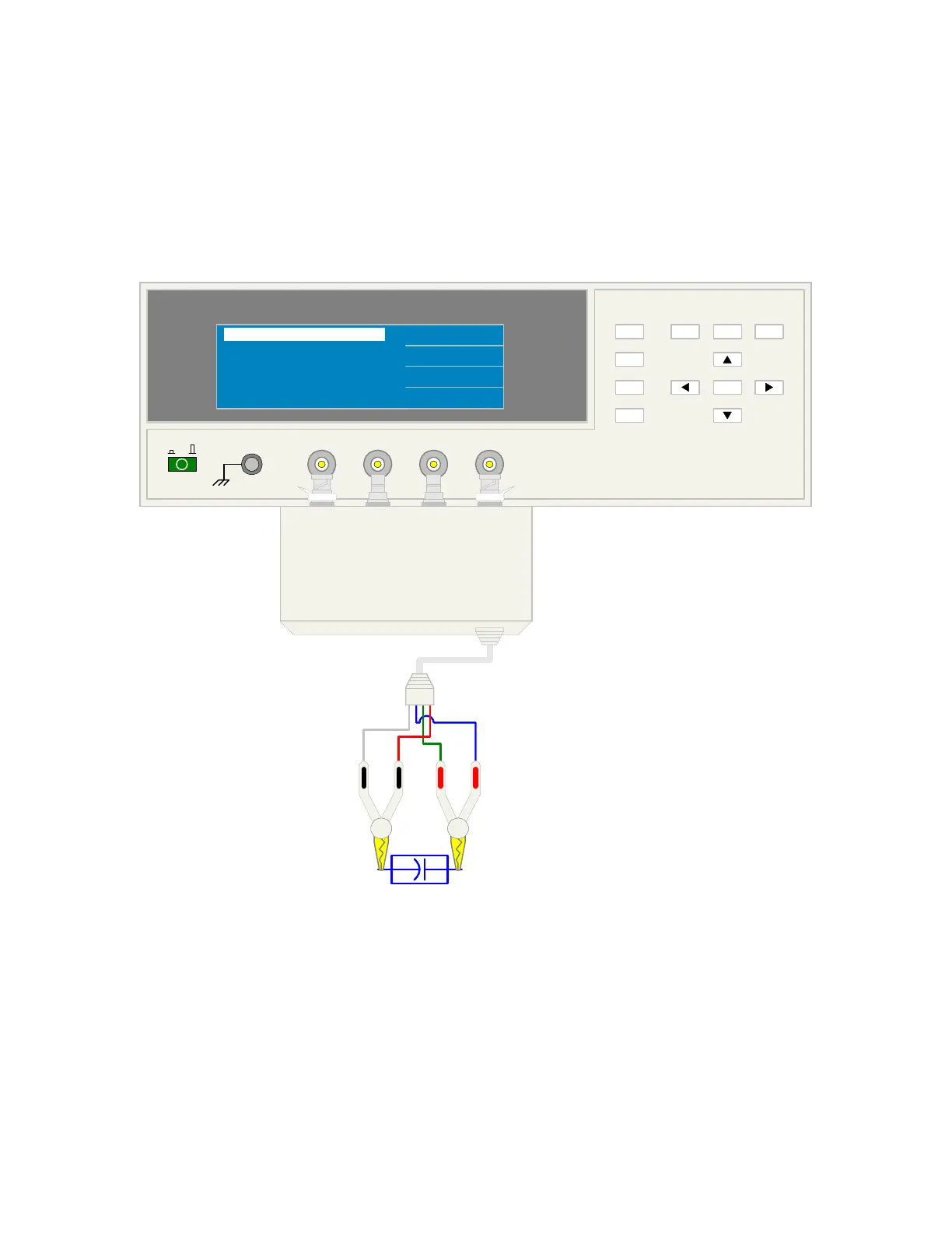
Figure 2-9 illustrates the connection of the 1730T LCR Meter to a single DUT using the 1700-03
Kelvin Clip Cable lead set. The red Kelvin clip/BNCs are connected between the H
POT
and H
CUR
(+) terminals on the 1730T unit and the high side of the device under test. The black Kelvin
clip/BNCs are connected between the L
POT
and L
CUR
(-) terminals on the 1730T unit to the low
side of the DUT.
+-
DUT
1730T LCR Meter
L
CUR
H
CUR
H
POT
L
POT
QuadTech
(-) (+)
F1
F4
F3
F2
F1
F3
F2
MEAS
DISPLAY
F4
TRIGGER
MAIN
INDEX
SYSTEM
SETUP
01
l
L
CUR
L
POT
H
POT
H
CUR
(+)(-)
QuadTech 1700-03 Test Leads
<MAIN INDEX CORRECT OPEN>
ABORT
MULTI
SINGLE
Cp : 0.023 pF
FREQ.: 100.0kHz RANGE : 4
CALIB : 3
MEASURED PASS ... 100%
PRESS ANY KEY TO ESCAPE
Figure 2-9: 1700-03 Kelvin Clip Test Leads