Operation 150821/A4 Page 61 of 110
There are a variety of test leads and fixtures available for the 1730T LCR Meter as listed in
Table 2-5 and illustrated in Figure 2-9 through 2-14.
Table 2-5: 1730T LCR Meter Test Leads & Fixtures
Description QuadTech P/N Figure
Axial/Radial Component Test Fixture 1700-01 2-10
Axial/Radial Remote Test Fixture 1700-02 2-11
Lead Set: 4 BNC Connectors to 2 Kelvin Clips 1700-03 2-9
Lead Set: 4 BNC Connectors to Chip Component Tweezers 7000-05 2-12
BNC to BNC Cable Lead Set (1m) 7000-01 2-13
BNC to BNC Cable Lead Set (2m) 7000-02 2-13
Low Voltage Chip Component Test Fixture 7000-07 2-14
Transformer Test Fixture 630166 2-15
1320 Bias Current Source 1320 2-16
NOTE:
For proper operation, the H
CUR
/H
POT
/I
CUR
/I
POT
cable shields must be connected together at the DUT. This connection
is already made using the 1730T recommended accessory leads. If the shields are not tied together, then at higher
frequencies a resonance may occur which could cause erroneous capacitance readings.
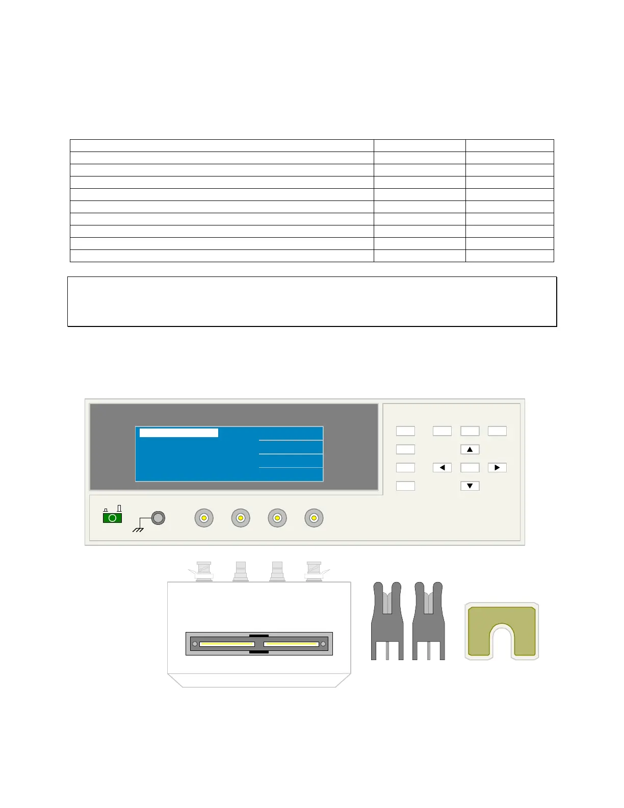
Figure 2-10 illustrates the connection of the 1700-01 axial/radial component test fixture to the
1730T LCR Meter. Insert the axial/radial leaded component in the test fixture paying attention
to the high and low designations on the test fixture.
Q
uadTech 1700-01 TEST FIXTURE
LOW HIGH
1700-01
1730T LCR Meter
L
CUR
H
CUR
H
POT
L
POT
QuadTech
(-) (+)
F1
F3
F2
MEAS
DISPLAY
F4
TRIGGER
MAIN
INDEX
SYSTEM
SETUP
01
l
F1
F4
F3
F2
<MEAS DISPLAY>
NEXT PAGE 1/4
PARA : Cs - D
LEVEL : 1.00 V
FREQ. : 100 kHz
Cs : 1.2345 pF
D : 1.2345
Axial Lead Adaptors
Rotated 90 degrees
as shown
Short
Figure 2-10: 1700-01 Axial/Radial Component Test Fixture