Page 16 of 110 150821/A4
Condensed Operating Instructions (Continued)
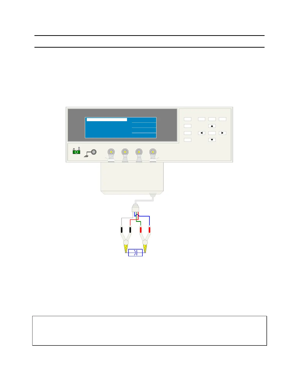
3. Connection to Device under Test (DUT)
Figure COI-3 illustrates the connection of the 1730T LCR Meter to a single DUT using the
1700-03 4-BNC to Kelvin Clips cable lead set. The silver BNC connectors are connected to
the front panel BNC terminals on the 1730 unit: red to H
CUR
/H
POT
and black to L
CUR
/L
POT
.
The red Kelvin clip is connected to the high side of the DUT and the black Kelvin clip to the
low side of the DUT.
+-
DUT
1730T LCR Meter
L
CUR
H
CUR
H
POT
L
POT
QuadTech
(-) (+)
F1
F4
F3
F2
01
l
L
CUR
L
POT
H
POT
H
CUR
(+)(-)
QuadTech 1700-03 Test Leads
< MEAS DISPLAY >
NEXT PAGE 1/4
LEVEL: 1.00 V
FREQ.: 1.0 kHz
Cs : 0.023 pF
Vm : 1000.00 mV
PARA.: Cs - D
D : 0.000
Im : 0.00 mA
COI-3: Connection to Device under Test
4. Make a Measurement
1. Press [MEAS DISPLAY]
2. Connect device under test (DUT) to test leads.
3. Press [TRIGGER].
4. Record measurement.
NOTE:
For proper operation, the H
CUR
/H
POT
/I
CUR
/I
POT
cable shields must be connected together at the DUT. This connection
is already made using the 1730T recommended accessory leads.
If the shields are not tied together, then at higher frequencies a resonance may occur which could cause erroneous
capacitance readings.