Page 70 of 110 150821/A4 Interface
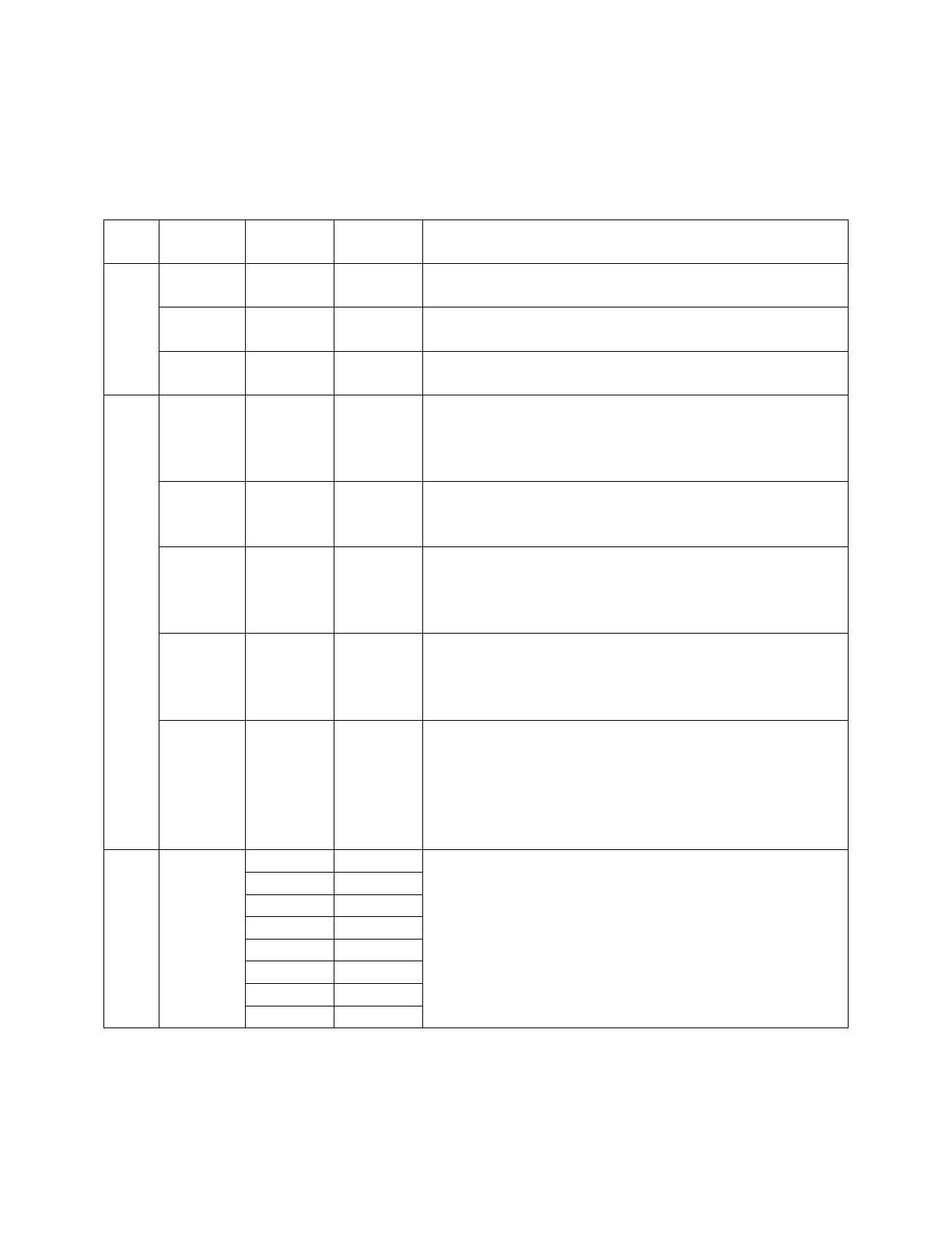
Table 3-1 lists the IEEE-488 Interface pin designations by pin number, signal name and pin
function. Bus and driver information is also listed.
Table 3-1: IEEE-488 Interface Pin Designations
Bus Driver Signal
Name
Pin
Number
Function
3 States DAV 6 Low State: “Data is Available” and valid on DI01
through DI08
Open
Collector
NRFD 7 Low State: At least one Listener on the bus is “Not
Ready For Data”
Handshake
Open
Collector
NDAC 8 Low State: At least one Listener on the bus is “Not
Accepting Data”
3 States ATN 11 “Attention” specifies 1 of 2 uses for the DI01 through
DI08 lines:
Low State: Controller command messages
High State: Data bytes from the Talker device
3 States IFC 9 “Interface Clear”
Low State: Returns portion of interface system to a
known quiescent state
Open
Collector
SRQ 10 “Service Request”
Low State: A Talker or Listener signals (to the
controller) need for attention in the midst of the
current sequence of events.
3 States REN 17 “Remote Enable”
Low State: Enables each device to enter remote mode
when addressed to listen.
High State: All devices revert to Local control.
Control
3 States EOI 5 “End of Identify”
If ATN is in HIGH state, then EOI LOW state
indicates the end of a multiple-byte data transfer
sequence.
If ATN is in LOW state, then EOI LOW state
indicates a parallel poll.
DI01 1
DI02 2
DI03 3
DI04 4
DI05 13
DI06 14
DI07 15
Data
Open
Collector
DI08 16
The 8-Line Data Bus.
If ATN is in LOW state, then the bus conveys
interface messages.
If ATN is in HIGH state, then the bus conveys device-
dependent messages. (Example: carries remote
control commands from the controller or from a talker
device)