QXS System and Cabinet Information 7
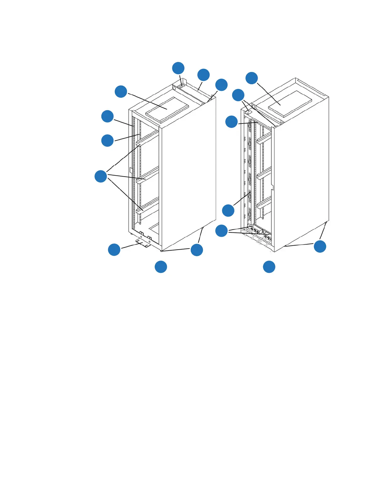
Figure 8 provides a standard cabinet identifying components (callouts) in the front and rear of the
unit. Callout descriptions are provided below the illustration.
Figure 8 Front and Rear View of Cabinet
Cabinet Vertical Support Rails
The cabinet vertical support rails can contain square holes, round holes, or pre-tapped holes. Refer to
the
QXS 12G Hardware Installation and Maintenance Guide
for rackmount installation information:
Cabinet Configurations with Chassis and Drives
Tab l e provides the maximum number of chassis and maximum number of drives that can be installed
within a standard 40U cabinet configuration.
1 Ventilation cover 2 Cable access opening
3 Rear plate 4 Support rails
5 Vertical support rails 6 Mounting rails
7 Stability foot 8 Leveling feet (variable adjust)
9 Power distribution 10 AC power entry boxes
11 Front of cabinet 12 Rear of cabinet

 Loading...


