14 QXS G2 (12G) Site Planning Guide
QXS-312 12G 2U12-Drive RAID Chassis Rear View
Refer to the numbers on the CRUs, Figure 12, and the table to identify components within the 2U
chassis. PSU and controller modules are available as CRUs. The RAID chassis use 2-port controller
modules. Use expansion chassis for optionally added storage.
RAID Chassis (CNC Controllers and 2 FC/iSCSI ports)
Figure 12 provides a rear view of the 2U12-drive RAID chassis with two CNC controllers (2 FC/iSCSI
ports).
Figure 12 2U12-Drive RAID Chassis (2 FC/iSCSI ports)
CNC FC/iSCSI Controller
Callout 1, Figure 12, is the Controller A location. Callout 2, Figure 12, is the Controller B location.
Both controllers are shown in the closed/locked position.
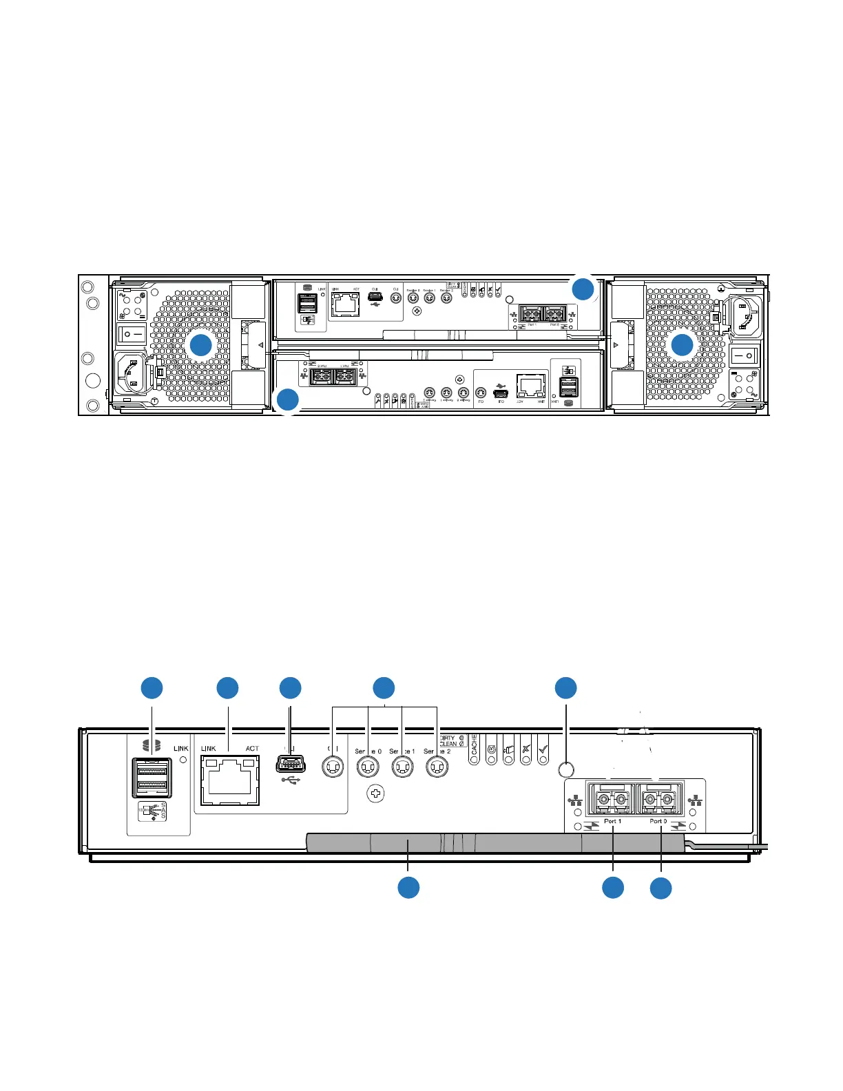
Figure 13 provides a rear view of the CNC FC/iSCSI controller used in the 2U12-drive systems. You can
configure the CNC host interface ports (Ports 0 and 1) with 8/16Gb/s FC SFPs; 10GbE iSCSI SFPs; or
1Gb/s RJ-45 SFPs.
Figure 13 CNC FC/iSCSI Controller
1
2
3
4
1
Controller A
2
Controller B
3
PSU0
4
PSU1
1
SAS Port
2
Ethernet Port
3
USB Port
4
Serial Ports (service only)
5
Reset
6
CNC Port 0
7
CNC Port 1
8
Lock/Release Handle

 Loading...


