QXS-484 12G System Specifications 39
CNC FC/iSCSI Controller
Callout 1, Figure 35, is the Controller A location. Callout 2 Figure 35, is the Controller B location. Both
controllers are shown in the closed/locked position.
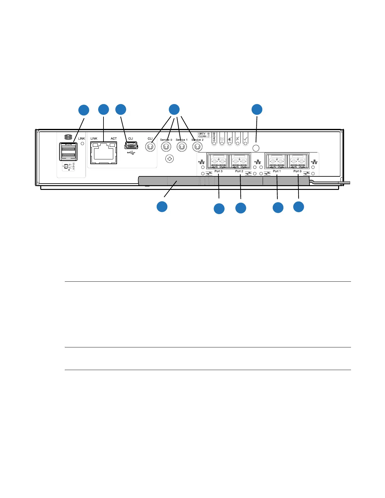
Figure 36 provides a rear view of the CNC FC/iSCSI controller used in the 5U84-drive systems. You can
configure the CNC host interface ports (Ports 0, 1, 2 and 3) with 8/16Gb/s FC SFPs; 10GbE iSCSI SFPs;
or 1Gb/s RJ-45 SFPs.
Figure 36 CNC FC/iSCSI Controller
5U84 Expansion Chassis (Rear View)
Figure 37 provides an illustration of the 5U84 expansion chassis rear view with two expansion IOMs
(2-SAS ports used) installed.
Refer to Figure 37 for all the 5U84 expansion chassis CRUs with expansion IOMs.
NOTE: The 5U84 expansion chassis uses the same expansion IOMs as the 2U12 and 2U24 expansion
chassis.
2 3 4 5
1
6
7
8
9
10
1
SAS Port
2
Ethernet Port
3
USB Port
4
Serial Ports (service only)
5
Reset
6
CNC Port 0
7
CNC Port 1
8
CNC Port 2
9
CNC Port 3
10
Lock/Release Handle

 Loading...


