16 QXS G2 (12G) Site Planning Guide
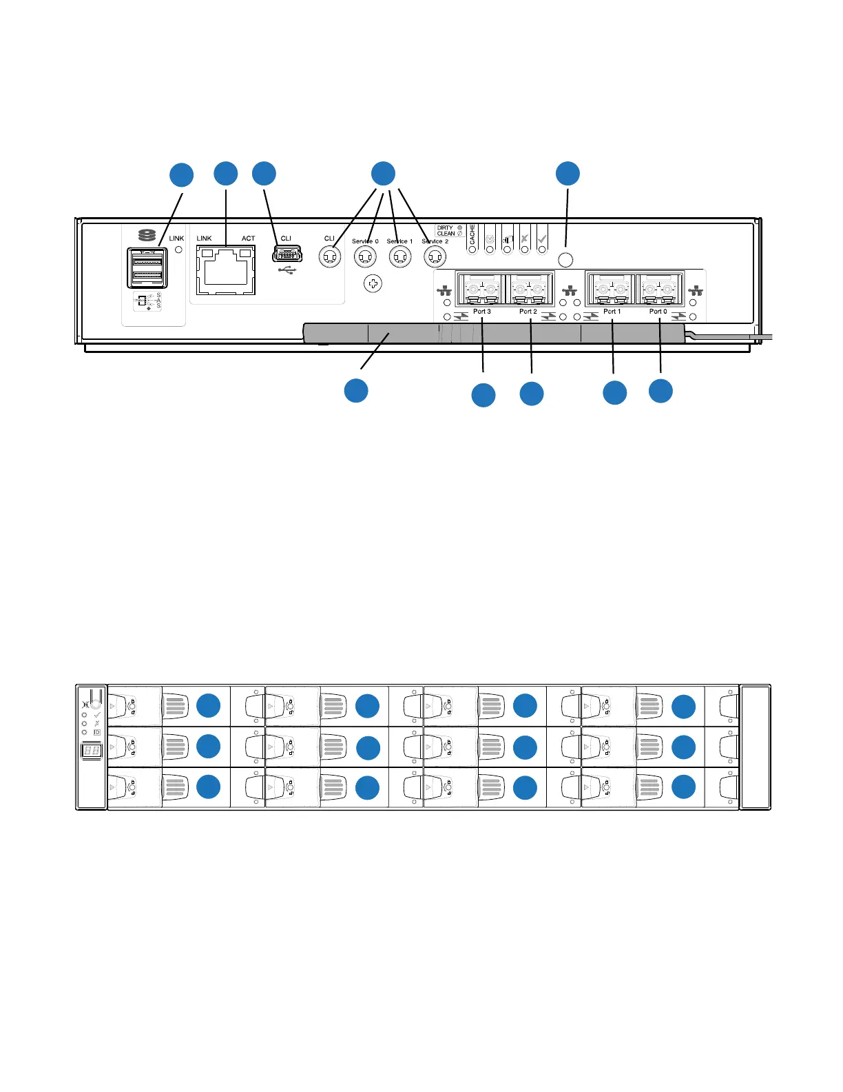
Figure 16 provides a rear view of the CNC FC/iSCSI controller used in the 2U12-drive systems. You can
configure the CNC host interface ports (Ports 0, 1, 2 and 3) with 8/16Gb/s FC SFPs; 10GbE iSCSI SFPs;
or 1Gb/s RJ-45 SFPs.
Figure 16 CNC FC/iSCSI Controller
2U12-Drive Expansion Front View
Integers on the drives indicate drive slot numbering sequence (0-11). Figure 17 provides a front view
of the 2U12-drive chassis.
Figure 17 2U12-Drive Chassis Front View
2U12-Drive Expansion Chassis Rear View
The top middle slot, Figure 18, is the Expansion IOM A location. The lower middle slot is the
Expansion IOM B location. Both IOMs are shown in the closed/locked position.
2 3 4 5
1
6
7
8
9
10
1
SAS Port
2
Ethernet Port
3
USB Port
4
Serial Ports (service only)
5
Reset
6
CNC Port 0
7
CNC Port 1
8
CNC Port 2
9
CNC Port 3
10
Lock/Release Handle

 Loading...


