18 QXS G2 (12G) Site Planning Guide
Power Supply Unit (PSU)
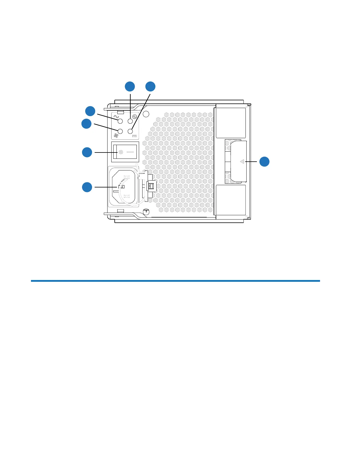
Figure 20 provides and illustration of the PSU used in the RAID chassis and the expansion chassis.
They are identical in the 12-drive and 24-drive chassis. Figure 20 shows an example of a PSU oriented
for use in the left PSU Slot 0 of the RAID or expansion chassis.
Figure 20 PSU
QXS-312/412 12G RAID and Expansion Physical
Requirements
The floor space at the installation site must be strong enough to support the combined weight of the
rack, 2U12 RAID chassis, 2U12 expansion chassis, and any additional equipment. The site also
requires sufficient space for installation, operation, and servicing of the chassis, together with
sufficient ventilation to allow a free flow of air to all chassis.
Composition
The RAID chassis and expansion chassis are comprised of sheet steel that is bonded together using
rivets, welding, and other forced contact methods. The metal surfaces are free from non-conductive
coatings and paint.
Chassis Designators
The RAID and expansion chassis designators are as follows:
• 2U12 chassis
3
4
1
5
2
6
7
1
Fan Fail LED
2
AC Fail LED
3
PSU OK LED
4
DC Fail LED
5
Release/Lock Handle
6
Power Connect

 Loading...


