12 QXS G2 (12G) Site Planning Guide
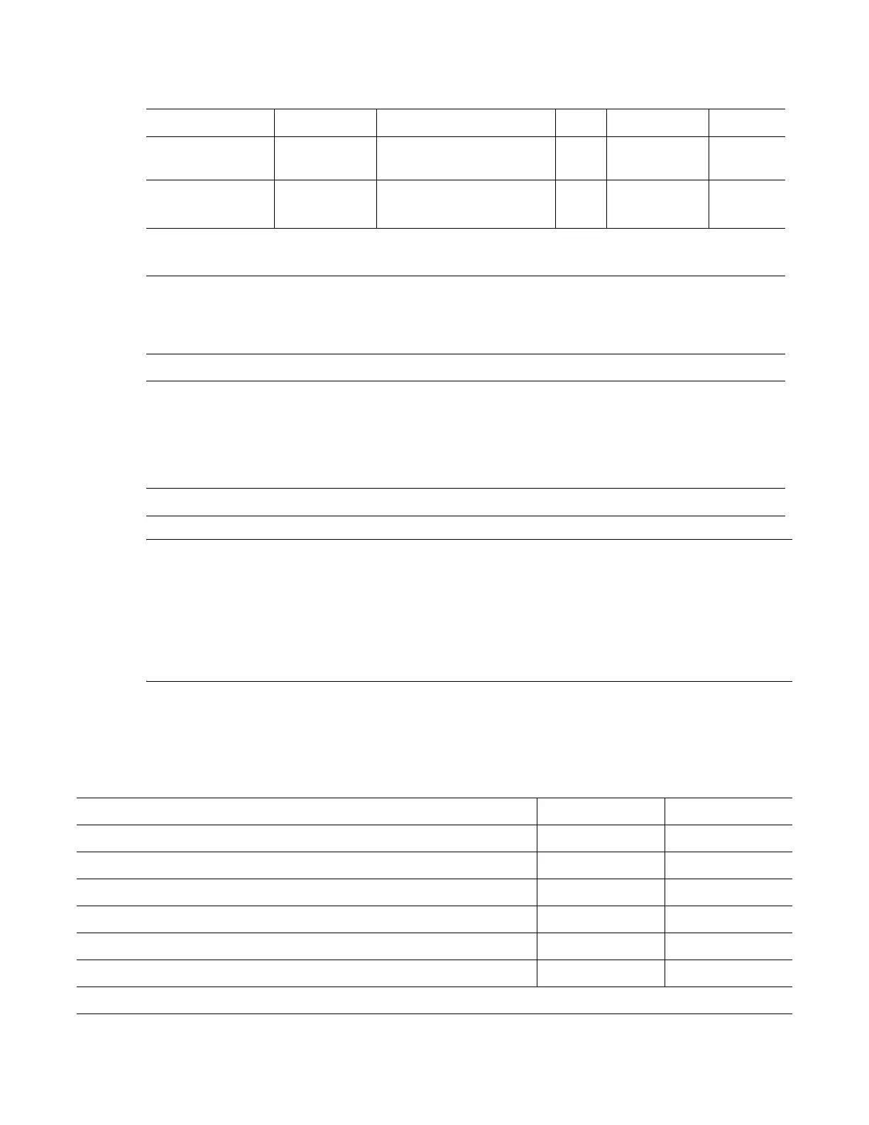
Tab l e 5 provides the QXS-312/412 12G chassis components/CRUs.
CAUTION: The RAID chassis supports dual-controller configuration only.
- If a partner controller fails, the storage system will fail over and run on a single controller module
until the redundancy is restored.
- A RAID controller or expansion IOM must be installed in IOM slot to ensure sufficient air flow
through the chassis during operation.
2U12-Drive RAID and Expansion Chassis Dimensions
Tab l e 6 identifies dimensions of the QXS-312/412 12G, 2U12-drive RAID and expansion chassis.
Ta b le 5 Chassis Components/CRUs
Product Configuration Drives PSUs
1
I/O Modules Bezel
4
2U12 RAID
Chassis
12Gb/s direct
dock drives
12 LFF (3.5” SATA) 2
2 Controllers
2
1
2U12 Expansion
Chassis
12Gb/s direct
dock drives
12 LFF (3.5” SATA) 2 2 Expansion
IOMs
3
1
PSUs
1
: Redundant PSUs must be compatible modules of the same type (both AC). Power cords are
shipped with all chassis.
Controllers
2
:
• The QXS-312 12G system has only 2-host ports per controller.
• The QXS-412 12G system has 4-host ports per controller.
IOMs
3
: Supported expansion IOMs are used in expansion chassis for adding storage.
Bezel
4
: Bezels ship as follows:
• The 2U12 chassis has a bezel shipped in a separate box and must be installed on site.
• The 2U24 chassis has a bezel shipped in a separate box and must be installed on site.
• The 5U84 chassis ships with the bezel installed.
Note: Ethernet cables are shipped with all RAID chassis.
Ta bl e 6 Chassis Dimensions
Specification Metric Unit Imperial Unit
Overall chassis height (2U) 87.9 mm 3.46 in
Width across mounting flange (located on front of chassis) 483 mm 19.01 in
Width across body of chassis 443 mm 17.44 in
Depth from face of mounting flange to back of chassis body 576.8 mm 22.71 in
Depth from face of mounting flange to rearmost chassis extremity 602.9 mm 23.74 in
Depth from face of Ops panel to rearmost chassis extremity 629.6 mm 24.79 in
Note: The 2U12 chassis uses 3.5" LFF disks.

 Loading...


